XECOM
(1)
XE0068
XE0068
1/99
FCC Registered Phone Line Interface
Description
The XE0068 is a compact, FCC registered telephone
line interface. Designers can use the XE0068 in their
telecom designs without going through the time and
expense of FCC Part 68 Registration. This makes the
XE0068 perfect for low volume and prototype designs.
To attain FCC part 68 Registration on the XE0068,
Xecom was required to control the output level to the
telephone line and provide a 2-second billing delay.
Xecom designed an Automatic Gain Control circuit to
meet FCC rules limiting transmit level. Xecom's Auto-
matic Gain Control circuit optimizes a wide range of in-
put signal levels for placement on the telephone line.
The XE0068 can support data, fax, voice, and DTMF
signalling applications.
F
eatures
*
Small Size - 1.75" x 1.08" x 0.42";
*
User Transferrable FCC Part 68 Registration;
*
Ring Detection and Hookswitch Control;
*
1500 Volt Isolation;
*
800 Volt Surge Protection;
*
Integrated supplemental lightening protection
*
Integral 2-Second Billing Delay;
*
Automatic Gain Control of transmit signal;
*
Integral 2 to 4 wire convertor;
*
Suitable for broad bandwidth applications;
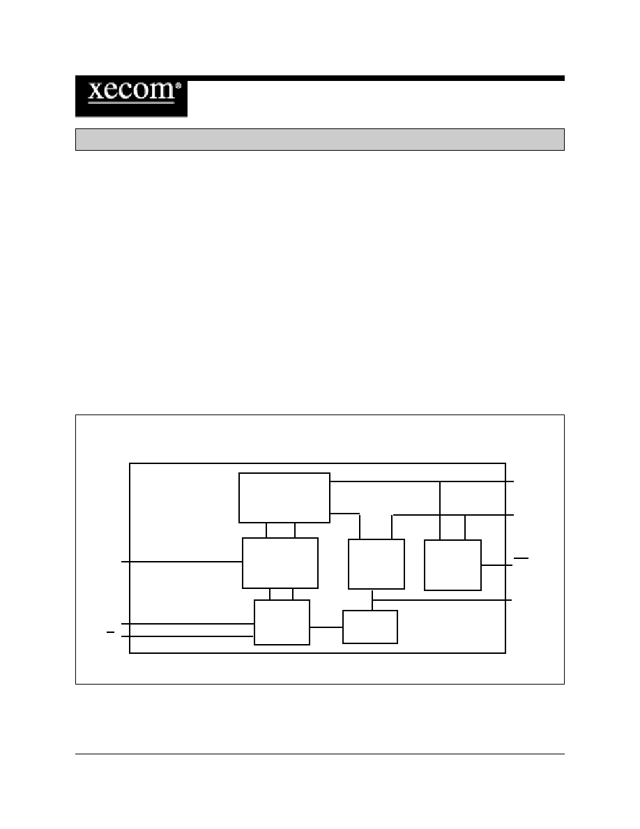
Ring
Detect
Hook-
switch
Control
Billing
Delay
2 to 4 wire
convertor
AGC
XMIT
RCVR
D/V
TIP
RING
RI
OH
Line
Transformer
BLOCK DIAGRAM
XECOM
(2)
XE0068
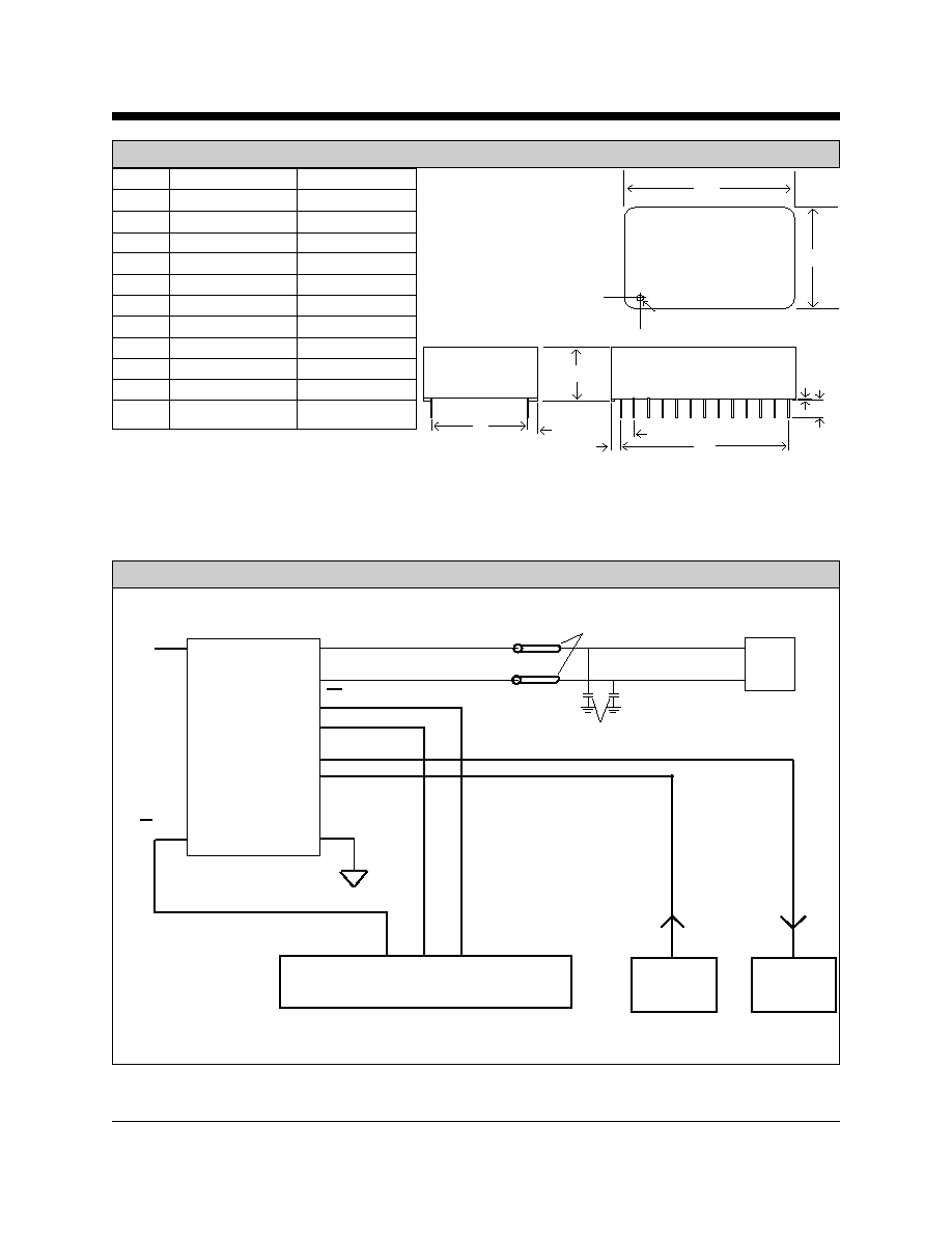
A
B
Denotes Pin 1
C
D
G
J
H
E
F
K
Inches
Metric(MM)
Dim
Min
Max
Min
Max
A
1.735
1.765
44.07
44.83
B
1.065
1.095
27.05
27.81
C
0.420
0.430
10.67
10.92
D
0.890
0.910
22.61
23.11
E
1.190
1.210
30.23
30.73
F
0.125
0.200
3.18
5.08
G
0.080
0.100
2.03
2.54
H
0.265
0.285
6.73
7.24
J
0.090
0.110
2.29
2.79
K
0.020
0.025
0.51
0.64
Pins are 0.025 inch square, tin plated.
Recommended PCB hole size is 0.056 inches (0.86 MM)
RJ11C
TIP
RING
+5V
RECEIVE SIGNAL
TRANSMIT SIGNAL
D/V
1
13
26
24
14
XE0068
3
4
22
21
19
18
RI
OH
RCVR
XMIT
System Controller
Signal
Source
Signal
Decoder
TPB270
Ferrite Beads
470 pFd
Mechanical Specifications
Typical Connection Diagram
XECOM
(3)
XE0068
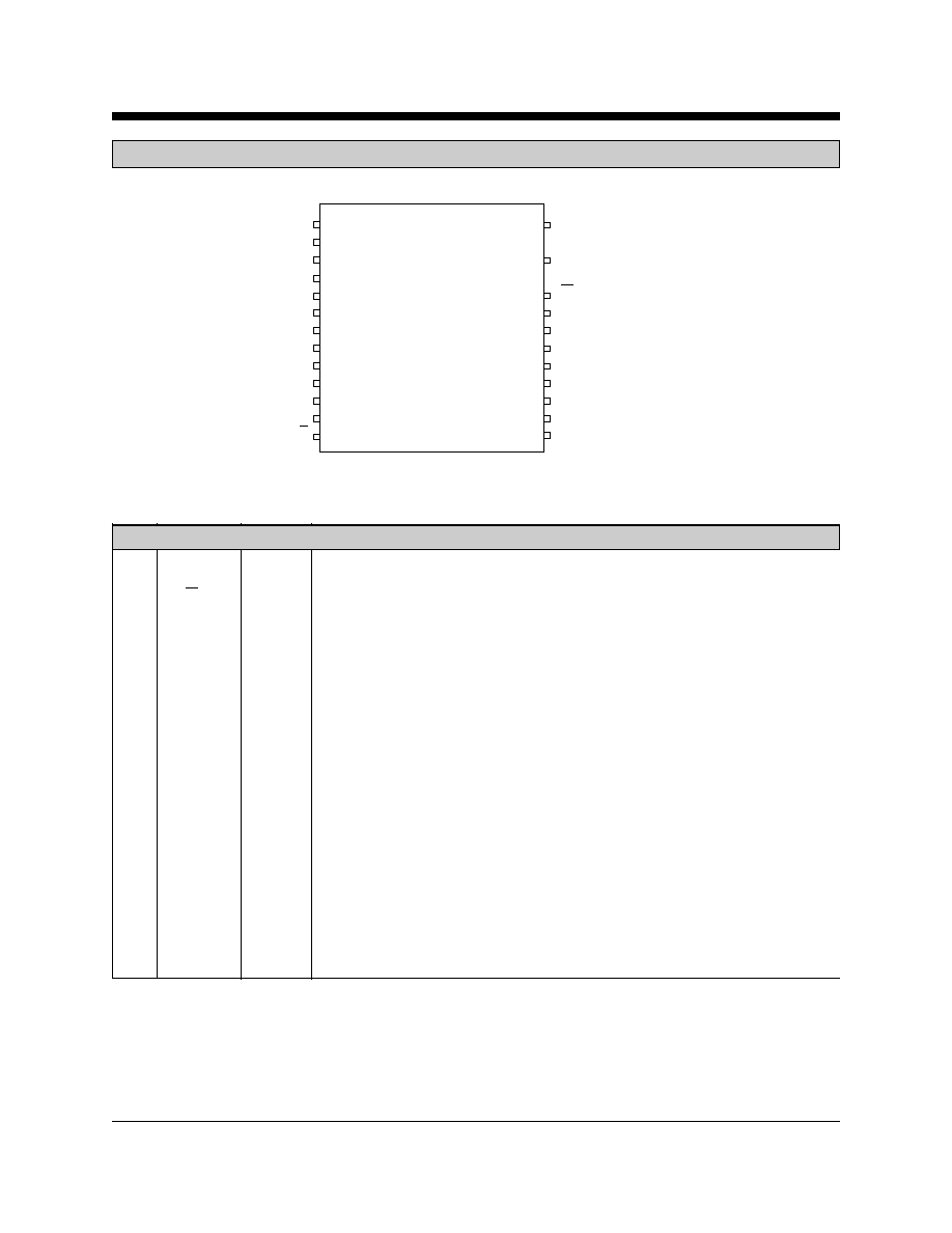
VCC
1
13
D/V
26
24
22
21
19
18
14
TIP
RING
RI
OH
RCVR
XMIT
GND
XE0068
20
17
16
15
N/C
N/C
N/C
N/C
2
3
4
5
6
7
8
9
12
11
10
N/C
N/C
N/C
N/C
N/C
N/C
N/C
N/C
N/C
N/C
N/C
XE0068 PIN CONFIGURATION
PIN DESCRIPTIONS
PIN
NAME
I/O
DESCRIPTION
1
VCC
---
+5 Volt power;
13
D/V
I
A TTL Low on Data/Voice selects a transmit level output of 0 dBm for voice or
DTMF signaling applications. A High on Data/Voice sets a maximum -9 dBm
transmit level for data transfer.
14
GND
---
Ground reference for the XE0068;
18
XMIT
I
XMIT is the Analog input signal to the XE0068. The input impedance on XMIT is
typically 10 Kohms at 1800 Hz. Signals placed on XMIT less than 0 dBm will be
placed on the telephone line at a maximum of -9 dBm when the Data/Voice signal
is driven high and a maximum of 0 dBm when Data/Voice is driven low.
19
RCVR
O
RCVR is the Analog output signal from the 2-4 wire converter. The output imped-
ance of RCVR is typically 10 ohms at 1800 hz. The signal level on RCVR will be
within 1 dBm of the received signal level present on the telephone line.
21
OH
I
Hookswitch control. A High on OH closes the internal relay to connect the equipment
to the phone line.
22
RI
O
Ring Indicate, output, active low, TTL, indicates the modem is receiving a ring signal.
24
Ring
---
Ring connection to the phone line (RJ11 Pin 4).
XECOM
(4)
XE0068
Supply Voltage
+6.5 Volts
Storage Temperature Range
-25
O
C to 8
5
O
C
Operating Temperature Range
0
O
C to 70
O
C
Lead Temperature
260
O
C
Maximum Soldering Duration
2 seconds
*
Exceeding these levels may result in permanent damage to the device.
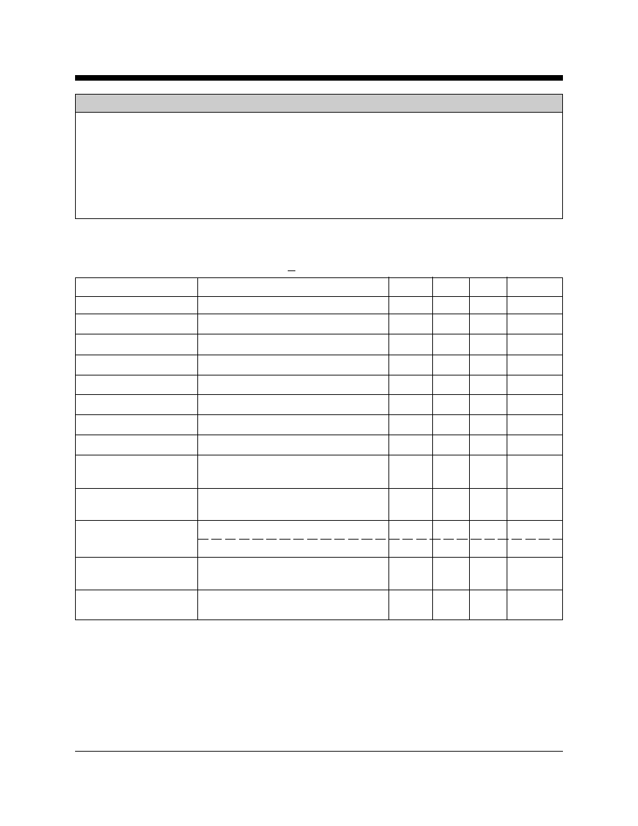
Electrical Specifications
(VCC = +5.0 Volts + 5%; Ta = 0o C to +70o C)
Parameter
Conditions
Min
Typ
Max
Units
Supply Current
Off hook
16
20
mA
Line Impedance
At 1000 Hz
540
600
660
Ohms
AGC Input Range
Output level <-9dBm; D/V high
-40
0
dBm
AGC Output Level
D/V held high
-20
-9
dBm
AGC Output Level
D/V held low
--11
0
dBm
Billing Delay
OH activated
2.0
2.3
sec
Transhybrid Loss
at 1000 Hz
40
dB
Receive Loss
at 1000Hz
-1.0
0.0
1.0
dB
Ring Detect Sensitivity
Min. AC voltage between Tip & Ring
38
Vrms
Type B ringer
Ring Indicate Output
Ring Voltage present on Tip & Ring
0.2
0.5
Volts
Voltage
Loop Current Switch
ON: (off-hook)
2.0
3.0
Volts
Control Voltage
OFF: (on-hook)
0.2
0.5
Volts
Loop Current Switch
OFF-Hook
0.1
2.0
mA
Control Current
Loop Current
OFF-Hook current draw from
0
20
100
mA
Absolute Maximum Ratings*
XECOM
(5)
XE0068
This product complies with Part 68 of the FCC Rules and Regulations. With each device shipped,there is a label which
contains, among other information, the FCC Registration Number and Ringer Equivalence Number
(REN) for this
product. You must, upon request, give this information to your telephone company.
Mounting this device in the final assembly must be made in such a manner as to preserve the high voltage protection
between the TIP/RING connection and the rest of the system. Typically, this may be accomplished by maintaining a
minimum spacing .100 mils between the TIP/RING trace to the RJ-11C Jack and low voltage portion of the system. No
additional circuitry may be attached between TIP/RING and the telephone line connection unless specifically allowed in
the rules.
The REN is useful to determine the quantity of devices you may connect to the telephone line and still have all of these
devices ring when the number is called. In most, but not all areas, the sum of the RENs of all devices connected to one
line should not exceed five (5.0). To be certain of the number of devices you may connect to the line, as determined by
the REN, you should contact the local telephone company to determine the maximum REN for your calling area.
If your system causes harm to the telephone network, the telephone company may discontinue service temporarily. If
possible, they will notify you in advance. If advance notification is not practical, you will be notified as soon as possible.
Your telephone company may make changes in its facilities, equipment, operations or procedures that could affect
proper functioning of your equipment. If they do, you will be notified in advance to give you an opportunity to maintain
uninterrupted service.
If you experience trouble with the device, please contact XECOM an (408) 945-6640 for information on obtaining
service or repairs. The telephone company may ask you to disconnect this device from the network until the problem has
been corrected or until you are sure that the device is not malfunctioning.
There are no repairs that can be made by the customer to the XE0068.
The device may not be used on coin service lines provided by the telephone company (this does not apply to private coin
telephone applications which use standard telephone lines). Connection to party lines is subject to state tariffs.
FCC Information
FCC Registration Number
DWEUSA-75283-DP-W
Ringer Equivalence
0.5B
Telephone Jack
RJ11C