
Specifications and information are subject to change without notice
WJ Communications, Inc
∑
Phone 1-800-WJ1-4401
∑
FAX: 408-577-6621
∑
e-mail: sales@wj.com
∑
Web site: www.wj.com
November
2003
The Communications Edge
TM
MH302
PCS/UMTS-band Quad-FET Mixer
Product Information
Product Features
∑
+27 dBm Input IP3
∑
RF 1800 ≠ 2000 MHz
∑
IF 200 ≠ 300 MHz
∑
Low-side LO configuration
∑
+13 dBm LO Drive Level
∑
High L-I & L-R Isolation (>30 dB)
∑
6-pin 3x3 mm DFN Package
∑
No External Bias Required
Product Description
The MH302 is a passive Quad-MOSFET mixer that
provides high dynamic range performance in a low cost
3 x 3 mm 6-pin DFN (Dual Flat No-Lead) package.
WJ's MH302 uses patented techniques to realize +27
dBm Input IP3 at an LO drive level of +13 dBm when
used in a simple application circuit with a low-side LO
configuration. The LO can also be driven with higher
power levels up +20 dBm to achieve higher IP3
performance. This mixer integrates internal circuitry to
provide single-ended interfaces for the RF & LO ports.
Typical applications include frequency up/down
conversion, modulation and demodulation for receivers
and transmitters used in 3G UMTS, PCS, and
DCS1800 mobile infrastructure.
Functional Diagram
MH302
IF1
GND
LO
IF2
GND
RF
4
5
6
3
2
1
Function Pin
No.
IF Differential Input
1
LO port
3
RF port
4
IF differential Input
6
Ground 2,
5
Specifications
Parameters
Units
Minimum
Typical
Maximum Comments
RF Frequency Range
MHz
1800
2000
LO Frequency Range
MHz
1540
1740
IF Frequency Range
MHz
200
260
300
See note 2
SSB Conversion Loss
dB
7.5
8.0 See
note
3
Input IP3
dBm
+23
+25
RF = 1.8 GHz, See note 4
Input IP3
dBm
+26
+27
RF = 1.9 GHz, See note 4
Input IP3
dBm
+23
+25
RF = 2.0 GHz, See note 4
Input 1 dB Compression Point
dBm
+16
+18
See
note
5
Noise Figure
dB
8
LO Input Drive Level
dBm
+13
LO-RF Isolation
dB
28
32
LO-IF Isolation
dB
29
35
Return Loss: RF Port
dB
15
Return Loss: LO Port
dB
10
Return Loss: IF Port
dB
15
1. Data was taken using an application board in a 50
system, with a low side LO at +13 dBm in a downconverting application at 25∞C with an IF frequency = 260 MHz.
2. An IF frequency of 260 MHz is a nominal frequency. The IF frequency can be specified by the user within the constraints of the specified minimum and maximum RF & LO frequency range.
3. The conversion loss includes the loss of an IF transformer (M/A COM ETK4-2T, nominal loss 0.7 dB at 260 MHz).
4. Input IP3 is measured using two tones with an input power of +3 dBm / tone separated by 1 MHz.
5. Although the input P1dB level is much higher, the continuous RF input power should not exceed +12 dBm. Operation above +12 dBm may cause permanent damage.
Absolute Maximum Ratings
Ordering Information
Parameters
Rating
Part No.
Description
Operating Case Temperature
-40∞ to +85
∞
C
MH302
PCS/UMTS-band Quad-FET Mixer
Storage Temperature
-40∞ to +125∞ C
MH302-PCB
Fully-Assembled MH302 Application Board
LO Input Power
+20 dBm
RF Input Power
+12 dBm
Operation of this device above any of these parameters may cause permanent damage.
Specifications and information are subject to change without notice
WJ Communications, Inc
∑
Phone 1-800-WJ1-4401
∑
FAX: 408-577-6621
∑
e-mail: sales@wj.com
∑
Web site: www.wj.com
November
2003
The Communications Edge
TM
MH302
PCS/UMTS-band Quad-FET Mixer
Product Information
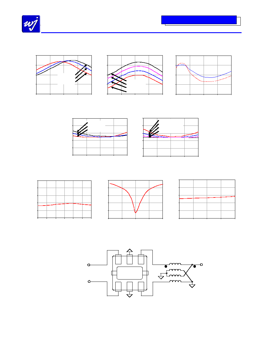
Typical Performance Charts
Input IP3 vs RF Frequency
+25∞ C, LO = +13 dBm
10
15
20
25
30
1700
1800
1900
2000
2100
RF Frequency (MHz)
In
p
u
t
IP
3
(
d
B
m
)
IF = 300 MHz
IF = 260 MHz
IF = 200 MHz
Input IP3 vs RF Frequency
+25∞ C, IF = 260 MHz
15
20
25
30
35
1700
1800
1900
2000
2100
RF Frequency (MHz)
In
p
u
t
IP
3
(
d
B
m
)
LO = +17 dBm
LO = +15 dBm
LO = +13 dBm
LO = +11 dBm
Isolation vs LO Frequency
25∞ C, LO = +13 dBm
25
30
35
40
45
1440
1540
1640
1740
1840
LO Frequency (MHz)
Isolation (dB)
L-R
L-I
Conversion Loss vs RF Frequency
+25∞ C, LO = +13 dBm
5
6
7
8
9
10
1700
1800
1900
2000
2100
RF Frequency (MHz)
C
o
n
v
er
si
o
n
L
o
ss (
d
B
)
IF = 300 MHz
IF = 260 MHz
IF = 200 MHz
Conversion Loss vs RF Frequency
+25∞ C, IF = 260 MHz
5
6
7
8
9
10
1700
1800
1900
2000
2100
RF Frequency (MHz)
C
o
n
v
er
si
o
n
L
o
ss (
d
B
)
LO = +11 dBm
LO = +13 dBm
LO = +15 dBm
LO = +17 dBm
Return Loss vs RF Frequency
+25∞ C, IF = 260 MHz, LO = +13 dBm
-25
-20
-15
-10
-5
0
1750
1800
1850
1900
1950
2000
2050
RF Frequency (MHz)
RF
Re
t
u
r
n
L
o
s
s
(
d
B)
Return Loss vs LO Frequency
+25∞ C, LO = +13 dBm
-25
-20
-15
-10
-5
0
1440
1540
1640
1740
1840
LO Frequency (MHz)
LO
R
e
t
u
r
n
Los
s
(
d
B
)
Return Loss vs IF Frequency
+25∞ C, RF = 1900 MHz, LO = +13 dBm
-25
-20
-15
-10
-5
0
200
225
250
275
300
IF Frequency (MHz)
IF
R
e
t
u
r
n
L
o
s
s
(
d
B
)
Application Circuit
4
5
6
3
2
1
RF
LO
IF
T2
6-lead
MLPM
3 x 3 mm
M/A-Com E-Series, ETK4-2T
RF 4:1 Transformer, 2.0 ≠ 1000 MHz
6-pin
DFN
Specifications and information are subject to change without notice
WJ Communications, Inc
∑
Phone 1-800-WJ1-4401
∑
FAX: 408-577-6621
∑
e-mail: sales@wj.com
∑
Web site: www.wj.com
November
2003
The Communications Edge
TM
MH302
PCS/UMTS-band Quad-FET Mixer
Product Information
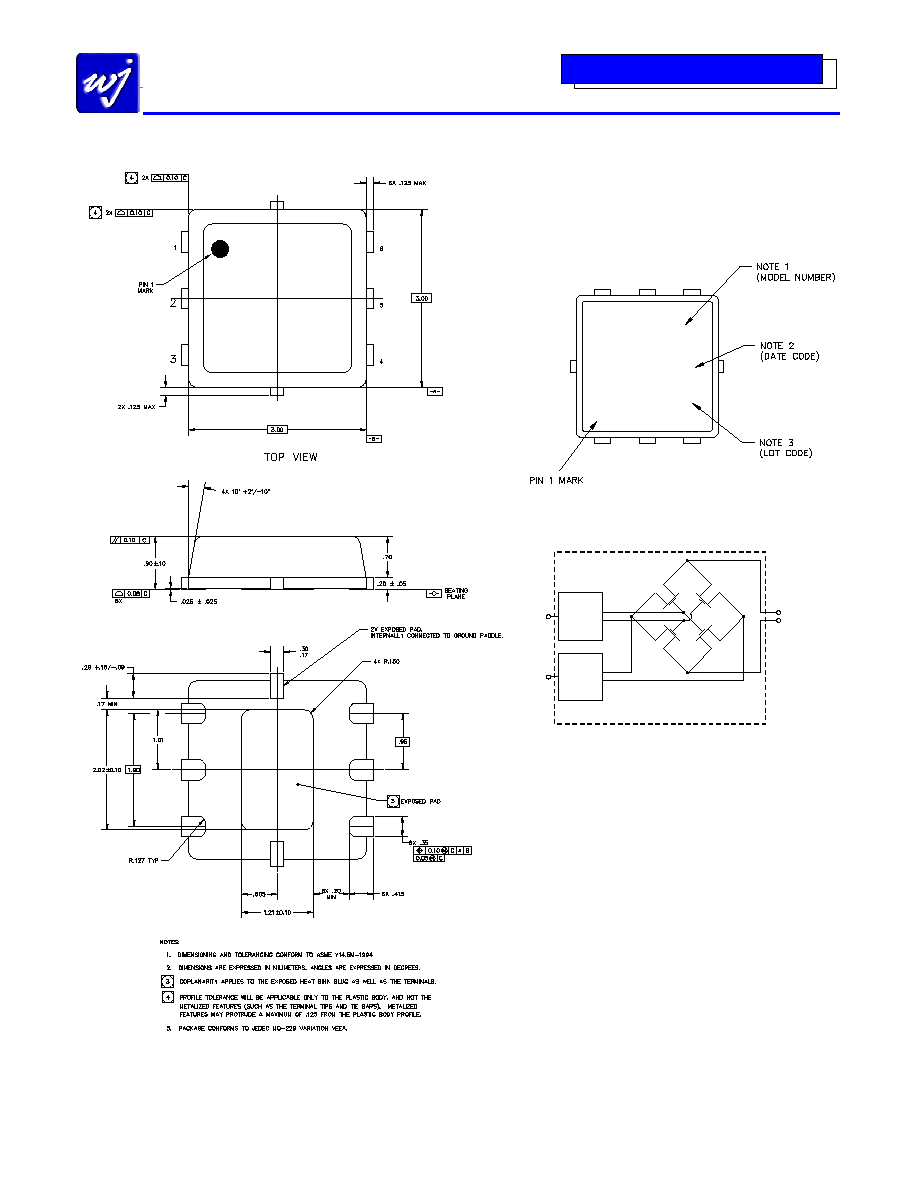
Package Information
XXX
YYWW M3
02
Product Marking
The component will be laser marked with a model number
"M302" designator exactly as shown followed by an
assembly date code in location shown by "YYWW". A
laser marked lot code will be in the location shown by
"XXX" and is unique for every assembly lot.
M302
YYWW
*
XXX
Functional Schematic Diagram
RF
LO
IF
180
o
Two-Way
Power
Divider
180
o
Two-Way
Power
Divider
MH302
ESD / MSL Information
ESD Classification: Class 1B
Value:
Passes at 500 V
Test:
Human Body Model (HBM)
Standard:
JEDEC Standard JESD22-A114
MSL Rating:
Level 1 at 235
∞
C reflow
Standard:
JEDEC Standard J-STD-020A