
Cool Solutions for Wireless Connectivity
XEMICS SA
∑
e-mail: info@xemics.com
∑
web: www.xemics.com
Datasheet
XE1610-OEMPVT 2.0/2.2
XE1610-OEMPVT
OEM GPS Receiver
Reference Design 2.0 / 2.2
GENERAL DESCRIPTION
The XE1610-OEMPVT GPS Receiver Reference
Design from XEMICS is a GPS receiver product
features the revolutionary FirstGPS
Æ
architecture. This
complete enabled GPS receiver solution provides high
position and speed accuracy performances as well as
high sensitivity and tracking capabilities in urban
canyon conditions. The solution enables small form
factor package. The XE1610-OEMPVT delivers major
advancements in GPS performances, accuracy,
integration, computing power and flexibility. It is
designed to simplify the embedded system integration
process.
The FirstGPS is a mixed hardware/software
architecture based on the XE16BB10 advanced
channel correlator IC and its companion RF down-
converter.
APPLICATIONS
∑
Automotive
∑
Asset
management/tracking
∑
Palmtop, Laptop, PDA
∑
Location Based Services enabled devices
∑
Handheld
receivers
KEY FEATURES
∑
High sensitivity: to -143 dBm tracking, superior
urban canyon performances
∑
Position accuracy: < 5m CEP (50%) without SA
(horizontal)
∑
Warm Start is under 32 seconds (50%)
∑
Hot Start is under 12 seconds (50%)
∑
Ultra low power: 17 mA @ 3V full power, 3
additional low power modes
∑
Embedded
ARM7TDMI
∑
Small form factor and low cost solution
∑
Ready-to-plug solution, fully autonomous PVT
solution. Easily integrated into existing systems
∑
On-board RAM for GPS navigation data, on-board
Flash memory back-up
∑
PPS
output
∑
Bidirectional NMEA interface
∑
Real Time Clock with separate back-up power
supply
REFERENCE
XE1610-OEMPVT 2.0.C ≠ 4MB Flash option
XE1610-OEMPVT 2.2.C ≠ 16MB Flash option

2 XX/D0308-199
Datasheet
XE1610-OEMPVT 2.0/2.2
Table of Contents
GENERAL DESCRIPTION.................................................................................................................................................. 1
APPLICATIONS .................................................................................................................................................................. 1
KEY FEATURES ................................................................................................................................................................. 1
REFERENCE ....................................................................................................................................................................... 1
1
FIRSTGPS ARCHITECTURE HIGHLIGHTS ............................................................................................................... 3
1.1
Industry Leading GPS Performance.......................................................................................................................... 3
1.2
Low Power ................................................................................................................................................................. 3
1.3
XE1610-OEMPVT GPS Receiver Reference Design Highlights............................................................................... 3
2
FUNCTIONAL BLOCK DIAGRAM .............................................................................................................................. 3
3
PIN DESCRIPTION ...................................................................................................................................................... 4
4
TECHNICAL CHARACTERISTICS.............................................................................................................................. 4
4.1
Specifications............................................................................................................................................................. 4
4.2
Physical Characteristics............................................................................................................................................. 5
4.3
Proposed Mechanical Interface ................................................................................................................................. 5
4.3.1
RF Interface Connector ............................................................................................................................................. 5
4.3.2
Data Interface Connector........................................................................................................................................... 5
5
INTERFACE DEFINITION, PRINCIPLES OF OPERATION ....................................................................................... 5
5.1
Data Interface ............................................................................................................................................................ 5
5.2
Operating Modes ....................................................................................................................................................... 6
5.3
NMEA Standard Message Set Specification ............................................................................................................. 7
5.3.1
NMEA Standard Sentences....................................................................................................................................... 7
5.3.2
GGA --Global Positioning System Fixed Data.......................................................................................................... 7
5.3.3
GLL--Geographic Position - Latitude/Longitude....................................................................................................... 8
5.3.4
GSA--GNSS DOP and Active Satellites ................................................................................................................... 8
5.3.5
GSV--GNSS Satellites in View ................................................................................................................................. 9
5.3.6
RMC--Recommended Minimum Specific GNSS Data ............................................................................................. 9
5.3.7
VTG--Course Over Ground and Ground Speed.....................................................................................................10
5.3.8
ZDA--Time & Date ..................................................................................................................................................10
5.4
NMEA Specific Sentences.......................................................................................................................................10
5.4.1
DI ≠ Diagnostic Message.........................................................................................................................................11
5.4.2
TF--Quick Test........................................................................................................................................................11
5.4.3
NM ≠ Sentence Mask and Automatic Output Rate..................................................................................................12
5.4.4
PS ≠ Pulse-Per-Second Configuration ....................................................................................................................12
5.4.5
PT ≠ Port Configuration ...........................................................................................................................................12
5.4.6
RT ≠ Reset the Receiver / Start-Stop FirstGPS ......................................................................................................13
5.4.7
VR ≠ Version Information.........................................................................................................................................13
5.4.8
TR ≠ Transparent Mode..........................................................................................................................................15
5.5
GPS Data Back-up...................................................................................................................................................17
5.6
Real Time clock .......................................................................................................................................................17
5.7
Split Search Mode....................................................................................................................................................17
5.8
Hardware Reset and System Watchdog .................................................................................................................17
6
DEFAULT SETTINGS ................................................................................................................................................18
6.1
GPS Engine Configuration.......................................................................................................................................19
6.1.1
Receiver configuration .............................................................................................................................................19
6.1.2
Filter configuration ...................................................................................................................................................19
6.1.3
Offset configuration..................................................................................................................................................19
6.1.4
Application settings..................................................................................................................................................19
7
APPLICATION INFORMATION .................................................................................................................................19
7.1
Active Antenna.........................................................................................................................................................19
EXHIBIT A..........................................................................................................................................................................20
EXHIBIT B..........................................................................................................................................................................22
3 XX/D0308-199
Datasheet
XE1610-OEMPVT 2.0/2.2
1 FIRSTGPS ARCHITECTURE HIGHLIGHTS
1.1
INDUSTRY LEADING GPS PERFORMANCE
-
Builds on high performance FirstGPS core
-
Satellite signal tracking engine to perform GPS acquisition and tracking functions without CPU intervention
-
High sensitivity: to -143 dBm tracking, superior urban canyon performances
-
Position accuracy: < 5m CEP (50%) without SA (horizontal)
-
Warm Start is under 32 seconds (50%)
-
Hot Start is under 12 seconds (50%)
-
Timing output accuracy: +/- 100 ns
1.2 LOW
POWER
-
Ultra low power integrated circuit design, optimized RF and DSP architectures, 17mA @ 3V tracking/doing fixes
(vers. 2.0 ≠ 4MB Flash option)
-
Further power saving thanks to 3 different power down modes
o
Power Save ≠ RF section and GPS engine turned Off
o
Stand-by ≠ RF section, GPS engine, and MCU clock turned Off, main power supply On, RTC running
o
Power down - RF section, GPS engine, and MCU clock turned Off, main power supply Off, RTC
running on the back-up supply
1.3
XE1610-OEMPVT GPS RECEIVER REFERENCE DESIGN HIGHLIGHTS
-
Embedded AT91 MCU, ARM7TDMI-based
-
Small form factor
- Low
cost
-
Ready-to-plug solution, fully autonomous PVT solution. Easily integrated into existing systems
-
High signal acquisition & tracking performances
-
On-board RAM for GPS navigation data. On-board Flash memory is used to back-up data such as the Almanac
- PPS
output
-
On-board RTC can be supplied by a separate back-up power supply if the main supply is turned off.
-
Application software can be customized for high volume applications (Flash memory)
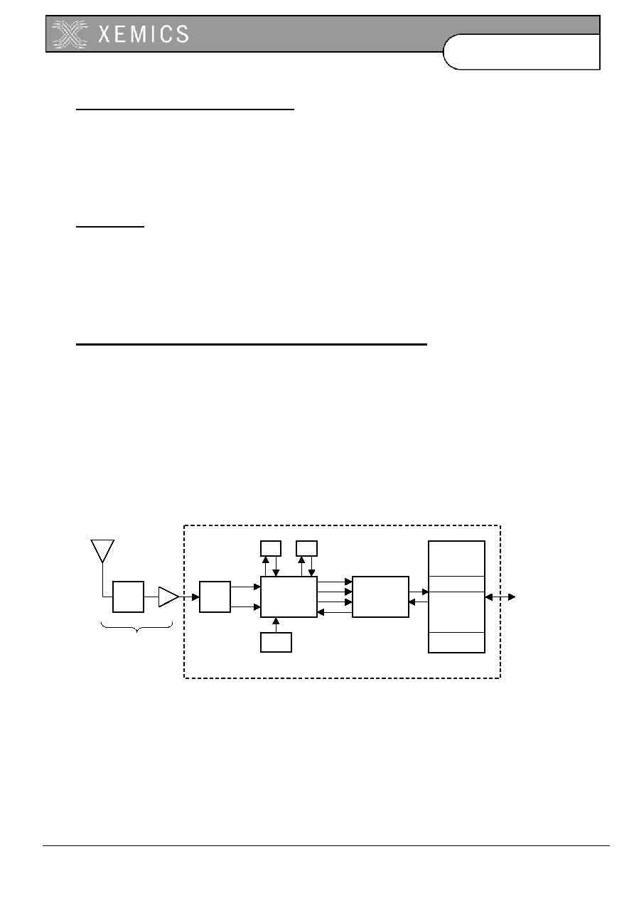
2 FUNCTIONAL BLOCK DIAGRAM
ANT
LNA
GPS
BASEBAND
PROCESSOR
RF
DOWN-
CONVERTER
BP
FILTER
TCXO
I LPF
Q LPF
I
Q
MCLKI
SCLK
RF+
RF-
BP
FILTER
RX
TX
RTOS
FirstGPS
SOFTWARE
API
XE1610-OEMPVT
APPLICATION
XE1610-OEMPVT
PVT
BOARD
INTERFACE
Active Antenna
ANT
LNA
GPS
BASEBAND
PROCESSOR
RF
DOWN-
CONVERTER
BP
FILTER
TCXO
I LPF
Q LPF
I
Q
MCLKI
SCLK
RF+
RF-
BP
FILTER
RX
TX
RTOS
FirstGPS
SOFTWARE
API
XE1610-OEMPVT
APPLICATION
XE1610-OEMPVT
PVT
BOARD
INTERFACE
Active Antenna

4 XX/D0308-199
Datasheet
XE1610-OEMPVT 2.0/2.2
3 PIN
DESCRIPTION
PIN NAME
DESCRIPTION
1
GND
Power and Signal Ground
2
ON/OFF
I
ON / Off command line
3
VCC
3.0 to 3.6 Volts DC Input Power Supply
4 USPED I
UART
Speed
5
RXA
I
Serial Receive Data, Port A, GPS NMEA Data
6
VRTCBK
Back-up supply for the RTC
7
TXA
O
Serial Transmit Data, Port A, GPS NMEA Data
8
PPS
O
One Pulse Per Second timing output
9
GND
Power and Signal Ground
10
RESETN
I
Manual Reset, Active low
11
ALMRDY
O
Almanac full and up to date, output
12
STY1 I
for customer specific version
13
N.C.
14
DELPOSN
I
Delete Initial Position
15
N.C.
16
STANDBYN
I
Stand-by (Active Low)
4 TECHNICAL
CHARACTERISTICS
4.1 SPECIFICATIONS
Min.
Typ.
Max.
Receiver
L1, C/A code
Correlators/Channels
32/8
Update Rate
1/minute
1/second
1/second
Satellite Reacquisition Time
1 second
HotStart
12 seconds (50%)
Warm Start
32 seconds (50%)
Cold Start
120 seconds (50%)
Tracking Sensitivity
-173 dBW
Power Consumption (VCC) @ 3.3 V
∑
Active mode, searching & tracking (v 2.0)
(v 2.2)
∑
Power save mode
∑
Stand-by
mode
∑
Power down mode
17 mA
19 mA
2.2 mA
400 uA
2 uA
Voltage Supply VCC
3 V
3.3 V
3.65 V
Back Up Voltage Supply VRTCBK
1.9 V
3.65 V
Output Protocol
NMEA 0183, v3.0
Position Accuracy
∑
Horizontal, SA off
∑
DGPS
corrected
5 meters CEP (50%)
1 meter
Timing output accuracy PPS output (rising edge)
- 100 nanosec.
100 nanosec.
5 XX/D0308-199
Datasheet
XE1610-OEMPVT 2.0/2.2
4.2 PHYSICAL
CHARACTERISTICS
The XE1610-OEMPVT is demonstrated as a 25 x 30 x 9.5 mm (approx. 1.0" x 1.2" x 0.38") module. This design has an
operating temperature range between -40C and +85C
4.3
PROPOSED MECHANICAL INTERFACE
4.3.1 RF Interface Connector
Subminiature HFL. Works with 3.0V active antenna
4.3.2 Data Interface Connector
16 contact board-to-board flat cable connector
5 INTERFACE DEFINITION, PRINCIPLES OF OPERATION
5.1 DATA
INTERFACE
VCC ≠ This is the main power supply
GND ≠ This is the power and signal ground
VRTCBK ≠ This is the back-up supply for the on-board hardware Real Time Clock
All I/Os on the Data Interface are related to VCC and GND levels.
ON/OFF - The ON/OFF input pin control whether the GPS engine is turned ON or OFF. If this pin is "high" whenever a
reset condition occurs or if it is turned "high" when in operation, then the GPS engine is turned on. If this pin is "low"
whenever a reset condition occurs then the GPS engine is not started. If this pin is turned "low" when in operation then
the GPS engine is turned off. When ON/OFF is "low", the on/off state can be superseded with the PXEMaRT
manufacturer specific NMEA sentence on RXA, as defined hereafter. This input pin has a pull-up resistor.
RXA ≠ Serial Receive data. This input pin has a pull-up resistor.
TXA ≠ Serial Transmit data
USPED ≠ Hardware Baudrate selection
The Serial NMEA data port (lines RXA and TXA) is an asynchronous serial port (UART). Upon reset, if the USPED input
pin is "low" the setting for this port is defined by the set A of UART parameters #19 to #22 in the Default Parameters
Table *, or if USPED is "high" the setting is defined by the set B #23 to #26. This setting can be modified with the
PXEMaPT manufacturer specific NMEA sentence defined hereafter. This input pin has a pull-up resistor. There is no
flow control on the UART.
(*) see the Default Settings section below
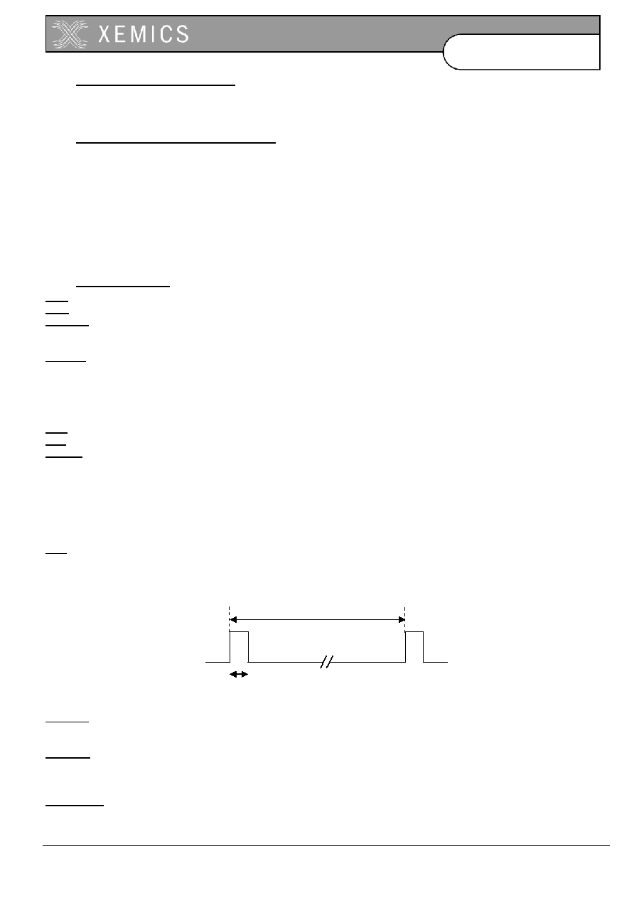
PPS - The PPS output pin is Pulse Per Second highly accurate timing signal generated by the on-board GPS baseband
processor. The PPS signal is available only when the receiver does position fixes. Otherwise its output level is "low".
After a reset condition, the setting for this port is defined in the Default Parameters Table *, parameter #1. This setting
can be modified with the PXEMaPS manufacturer specific NMEA sentence defined hereafter.
(*) see the Default Settings section below
The rising edge of the PPS signal is synchronous with the GPS time.
RESETN ≠ Manual Reset input pin. The receiver has 2 reset conditions: first, on power-on, thanks to an on-board
Power On Reset circuitry; and an external reset when the RESETN pin is "low". This input pin has a pull-up resistor.
ALMRDY ≠ When in Active mode, this output indicates the on-board Almanac status. Upon start up and whenever the
Almanac data are tested invalid or not up-to-date the output level is "low. If tested valid and up-to-date the output level is
"high".
STANDBYN ≠ This input sets the receiver in Stand-by mode when its level is "low". Otherwise the receiver is either in
Active or Power Save modes. See below, under Operating modes for details. This input pin has a pull-up resistor.
1 second
~ 83 ms.