1
RF Monolithics, Inc.
Phone: (972) 233-290
Fax: (972) 387-8148
E-mail: info@rfm.com
RFM Europe
Phone: 44 1963 251383
Fax: 44 1963 251510
http://www.rfm.com
IC1003-050103
©1999 by RF Monolithics, Inc. The stylized RFM logo are registered trademarks of RF Monolithics, Inc.
Page of 11
∑
Provides RF Uart Functions, 12 Bit Symbols to Serial TX
∑
And Serial RX to 12 bit Symbols with Start Symbol Detection
∑
Supports data rates from 100Kbps to 1Mbps
∑
Allows unsquelched receiver operation for improved sensitiviy
∑
Compatible with RFM's TR-Series ASH transceivers
The IC1003
RF Uart IC
detects a start-of-data pulse sequence and then provides
clocking pulses in the middle of each following data bit. The IC1003 is designed to
support a host protocol processor which can be in sleep mode until interrupted into
active operation by the start-of-data detect pulse. The IC1003 is compatible with RFM's
2nd generation ASH transceivers and receivers and allows these radios to operate with
no threshold for improved system sensitivity.
Absolute Maximum Ratings
Please refer to the latest revision of Xilinx data sheet for the XC9572-7VQ64
IC1003
RF Uart
IC
Characteristic
Sym
Notes
Minimum
Typical
Maximum
Units
Supply Voltage
VDD
3.0
3.5
V
Supply Current
At 40Mhz Clock(1Mbs Data)
IDD
48
mA
Logic Low Input
VIL
0.8
0.2
VDD
Logic High Input
VIH
VDD
Logic Low Output
VOL
VDD - 0.7
0.6
V
Logic High Output
VOH
V
Supported Data Rates:
100
1000
Kbps
Transmitted Bit Rate Tolerance
±1
%
Operating Temperature Range
-40
85
∞C

2
RF Monolithics, Inc.
Phone: (972) 233-290
Fax: (972) 387-8148
E-mail: info@rfm.com
RFM Europe
Phone: 44 1963 251383
Fax: 44 1963 251510
http://www.rfm.com
IC1003-050103
©1999 by RF Monolithics, Inc. The stylized RFM logo are registered trademarks of RF Monolithics, Inc.
Page of 11
RF Uart IC1003
Note that the ASH radio RX Data output signal is inverted before
being applied to the IC1003. The steady high pulse that begins
the start-of-data pulse sequence to the IC1003 is generated by
the reception of an eight-bit long RF transmission. This pulse
also helps "train" the base-band coupling capacitor in the ASH
radio for best data slicer noise rejection. The host processor
should generate inverted data for transmission by the ASH radio
and should input the same inverted data that drives the IC1003.
Data Encoding
Data should be encoded to provide frequent logic state
transitions (edges) to facilitate data clock alignment, and should
exhibit good dynamic DC-balance (50% high bits and 50% low
bits over any interval of 16 bits or less) to maintain the radio's
base-band capacitor training for best noise performance. The
popular encoding method is byte-to-12 bit symbolizing, which
encodes each byte as a pattern of 12 bits, always with six one
bits and six zero bits. Symbolizing requires fewer bits than
Manchester to encode a message, and also provides frequent
state transitions and good DC-balance. An example of 12-bit
symbolizing can be found in page 4.
Note that the IC1003 has no provisions for detecting end-of-
data. This provides flexibility in message length and data
encoding, but requires the message length and/or an end-of-
data symbol to be embedded in the data by the user and Start
Symbol Reset brought high will clear Start Symbol Detect.
Operation
A typical IC1003 application the RX Data output from the 2nd
generation ASH transceiver (or receiver) is applied to the IC1003.
In receive mode the IC1003 detects the presence of a specific
unique Start Symbol sequence and outputs a Start Detect. The
IC1003 generates data clocking (data valid) and shifts the data into
a 12 bit shift register and will rise the data Ready pin when a
Symbol is ready to be read. After the packet is received the Start
Detect Signal must be reset by Start Detect reset pin going high.
The IC1003 used as an transmitter interface will write in a 12 bit
symbol and while TX Enable is high will shift out the data out the
data out pin at the Clock Frequency dived by 40(40Mhz clock will
obtain a 1Mbps data rate). The IC1003 supports data rates from
100K ≠ 1000K bits per second (bps)..
The IC1003 is implemented in an industrial temperature range
of
Xilinx data sheet for the XC9572-7VQ64
CPLD. Please refer
to the latest revision of Xilinx data sheet for detailed electrical and
mechanical specifications.
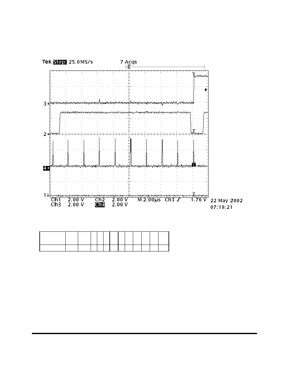
Start-of-Data Pulse Sequence Generation
The IC1003 start-of-data pulse sequence is a steady High pulse of
eight bit periods, followed by a sequence of eight bits in an
alternating high-low-high-low... pattern. This pulse sequence is
very unlikely to occur in a stream of white noise (data sliced),
providing good false triggering performance. The IC1003 outputs
the Start Detect pulse when the RX Data input line to the IC1003
has remained a steady low for eight bit periods. After eight bit
periods of a steady high, the data input should begin the eight-bit
sequence of alternating high and low bits. The eight-bit alternating
high-low sequence provides data clocking alignment training under
low signal-to-noise conditions (data edge jitter) and should be used
for best results.

3
RF Monolithics, Inc.
Phone: (972) 233-290
Fax: (972) 387-8148
E-mail: info@rfm.com
RFM Europe
Phone: 44 1963 251383
Fax: 44 1963 251510
http://www.rfm.com
IC1003-050103
©1999 by RF Monolithics, Inc. The stylized RFM logo are registered trademarks of RF Monolithics, Inc.
Page of 11
Pin Name
Pin Discription
TX Data 0
31
Data bit 0 of Transmit Symbol, true data
TX Data 1
47
Data bit 1 of Transmit Symbol, true data
TX Data 2
5
Data bit 2 of Transmit Symbol, true data
TX Data 3
8
Data bit 3 of Transmit Symbol, true data
TX Data 4
10
Data bit 4 of Transmit Symbol, true data
TX Data 5
6
Data bit 5 of Transmit Symbol, true data
TX Data 6
16
Data bit 6 of Transmit Symbol, true data
TX Data 7
17
Data bit 7 of Transmit Symbol, true data
TX Data 8
59
Data bit 8 of Transmit Symbol, true data
TX Data 9
4
Data bit 9 of Transmit Symbol, true data
TX Data 10
49
Data bit 10 of Transmit Symbol, true data
TX Data 11
56
Data bit 11 of Transmit Symbol, true data
TX Write/
32
Transfers TX Data to shift register on falling edge of high to low
TX Enable
57
Enables serial data out to TR1100
RX Data 0
40
Data bit 0 of Receive Symbol, true data
RX Data 1
39
Data bit 1 of Receive Symbol, true data
RX Data 2
38
Data bit 2 of Receive Symbol, true data
RX Data 3
36
Data bit 3 of Receive Symbol, true data
RX Data 4
35
Data bit 4 of Receive Symbol, true data
RX Data 5
34
Data bit 5 of Receive Symbol, true data
RX Data 6
33
Data bit 6 of Receive Symbol, true data
RX Data 7
18
Data bit 7 of Receive Symbol, true data
RX Data 8
42
Data bit 8 of Receive Symbol, true data
RX Data 9
62
Data bit 9 of Receive Symbol, true data
RX Data 10
50
Data bit 10 of Receive Symbol, true data
RX Data 11
22
Data bit 11 of Receive Symbol, true data
RX Read/
11
Transfers RX Data to Output register on falling edge of high to low
Data Ready
44
Receive Symbol Read, cleared by RX Read/, Active High
TX Busy
43
TX Buffer Full, Active High
Start Detect
60
Start Symbol Detected, cleared by Start Symbol Reset, Active High
Start Detect Reset
7
Start Symbol Rest, Active High
RX Enable
58
Enables Start Symbol Detection, Active High
TX OUT
19
TX Serial Data output TR1100, Active High
RX IN
2
RX Serial Data input TR1100, Active High
Reset
64
Reset, Active Low
Clock in
15
Clock In, valid speeds of 8Mhz to 40Mhz, Clock in
˜
40 = Baud Rate
40Mhz = Data Rate of 1Mbs, 20Mhz = Data Rate of 500Mbs
10Mhz = Data Rate of 250Kbs
RF Uart IC1003