 | –≠–ª–µ–∫—Ç—Ä–æ–Ω–Ω—ã–π –∫–æ–º–ø–æ–Ω–µ–Ω—Ç: Y1112 | –°–∫–∞—á–∞—Ç—å:  PDF PDF  ZIP ZIP |
THE FLUORACTOR
Æ
Y1112
FLUORESCENT LAMP STARTER SWITCH
P R O D U C T I N F O R M A T I O N
1
JUNE 1984 - REVISED SEPTEMBER 1997
Copyright © 1997, Power Innovations Limited, UK
Information is current as of publication date. Products conform to specifications in accordance
with the terms of Power Innovations standard warranty. Production processing does not
necessarily include testing of all parameters.
q
V
(BR)
1200 to 1500 V
q
I
H
> 175 mA
q
I
GT
< 2 mA
description
This product is intended for use as a T8/T12
fluorescent tube starter switch on 200-240 V a.c.
supplies with tube sizes up to 5ft with leading
and lagging ballast circuits.
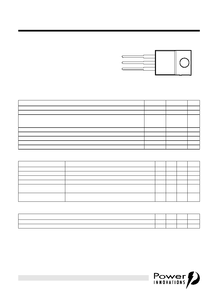
K
A
G
TO-220 PACKAGE
(TOP VIEW)
Pin 2 is in electrical contact with the mounting base.
MDC1ACA
1
2
3
absolute maximum ratings at 25∞C case temperature (unless otherwise noted)
RATING
SYMBOL
VALUE
UNIT
Crest working off-state voltage (Full wave rectified 50 Hz a.c.)
V
DWM
375
V
Peak reverse gate voltage
V
RGM
6
V
On-state current
-- continuous
-- repetitive peak
-- non-repetitive peak
I
T
I
TRM
I
TSM
1.5
2
10
A
Peak gate current
I
GRM
0.5
A
Average gate power
P
G(av)
0.3
W
Operating case temperature range
T
C
-5 to +85
∞C
Storage temperature range
T
stg
-10 to +110
∞C
Lead temperature during soldering 1.6 mm from the case for 10 seconds
T
lead
230
∞C
electrical characteristics at 25∞C case temperature (unless otherwise noted)
PARAMETER
TEST CONDITIONS
MIN
TYP
MAX
UNIT
I
D
Off-state current
V
D
= V
DWM
T
j
= 65∞C
1
mA
V
T
On-state voltage
I
T
= 2 A
3.1
V
V
(BR)
Clamping voltage
I
BR
= 5 mA
t
p
< 200 µs, 2% duty cycle
1200
1500
V
I
H
Holding current
See application circuit
175
mA
I
GTM
Peak gate
trigger current
V
AA
= 10 V
R
L
= 10
2
mA
V
GTM
Peak gate
trigger voltage
V
AA
= 10 V
R
L
= 10
3
V
thermal characteristics
PARAMETER
MIN
TYP
MAX
UNIT
R
JA
Junction to free air thermal resistance
62.5
∞C/W
R
JC
Junction to case thermal resistance
3.5
∞C/W

THE FLUORACTOR
Æ
Y1112
FLUORESCENT LAMP STARTER SWITCH
2
JUNE 1984 - REVISED SEPTEMBER 1997
P R O D U C T I N F O R M A T I O N
applications data
The conventional method of starting fluorescent tubes employs the use of an electromechanical canister. This
consists of a bimetallic strip which opens as it cools and in conjunction with the ballast inductor, provides the
tube striking voltage. However, the random nature of the pulsing results in repeated striking attempts and
degradation of both the tube and starter. The tube degradation is illustrated by its progressively blackening
ends and ultimately required tube replacement.
The Y1112, "Fluoractor
Æ
", has been specifically introduced for use in electronic starters. This unique device
offers the lighting industry an opportunity to develop electronic starters small enough to be retrofit
replacements for the established electromechanical canisters. Its double thyristor structure with integrated
zener clamp diode and current mirror provides the technology for a starter with enhanced features such as
controlled flicker free start up, automatic tube shutdown at end of tube life and reduced degradation of tube
ends leading to extended life. The increased functionality, lifetime and reliability of these starters has led in
some cases to them being embodied in the ballast itself, a development not feasible with the old
electromechanical canisters.
NOTE
1: These rectifiers need to be voltage selected for V
R
V
(BR)max
+ 150 V
Figure 1. Two terminal starter circuit
FLSCCT1
Y1112
150 k
R2
68 k
R3
6.8 k
D5
D6
D7
D1 to 4 (see Note A)
4 x 1N4007
D5 to 7
3 x 1N4001
3
JUNE 1984 - REVISED SEPTEMBER 1997
THE FLUORACTOR
Æ
Y1112
FLUORESCENT LAMP STARTER SWITCH
P R O D U C T I N F O R M A T I O N
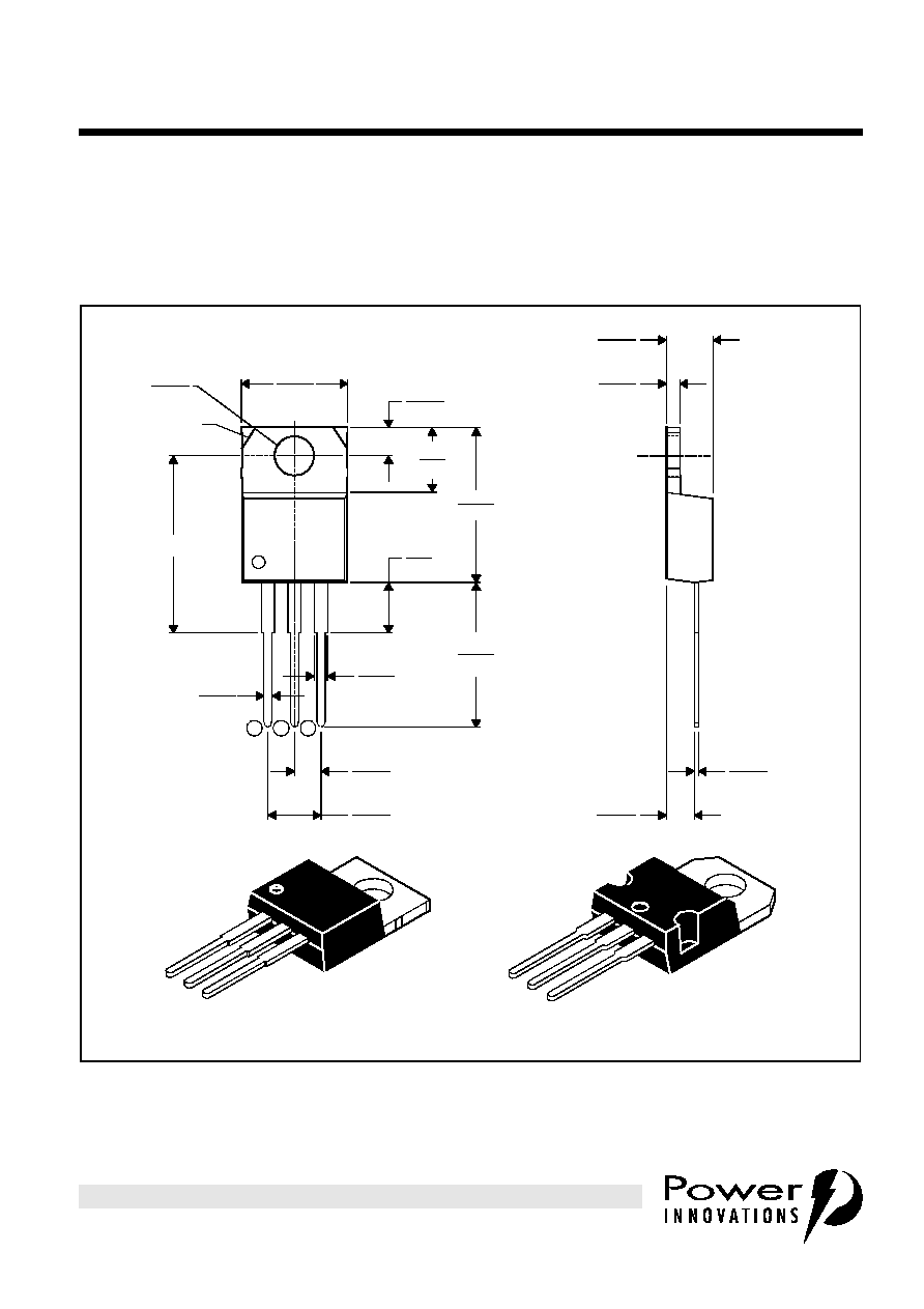
TO-220
3-pin plastic flange-mount package
This single-in-line package consists of a circuit mounted on a lead frame and encapsulated within a plastic
compound. The compound will withstand soldering temperature with no deformation, and circuit performance
characteristics will remain stable when operated in high humidity conditions. Leads require no additional
cleaning or processing when used in soldered assembly.
MECHANICAL DATA
TO220
ALL LINEAR DIMENSIONS IN MILLIMETERS
¯
1,23
1,32
4,20
4,70
1
2
3
0,97
0,61
see Note C
see Note B
10,0
10,4
2,54
2,95
6,0
6,6
14,55
15,90
12,7
14,1
3,5
6,1
1,07
1,70
2,34
2,74
4,88
5,28
3,71
3,96
0,41
0,64
2,40
2,90
VERSION 2
VERSION 1
NOTES: A. The centre pin is in electrical contact with the mounting tab.
B. Mounting tab corner profile according to package version.
C. Typical fixing hole centre stand off height according to package version.
Version 1, 18.0 mm. Version 2, 17.6 mm.
MDXXBE

THE FLUORACTOR
Æ
Y1112
FLUORESCENT LAMP STARTER SWITCH
4
JUNE 1984 - REVISED SEPTEMBER 1997
P R O D U C T I N F O R M A T I O N
IMPORTANT NOTICE
Power Innovations Limited (PI) reserves the right to make changes to its products or to discontinue any
semiconductor product or service without notice, and advises its customers to verify, before placing orders, that the
information being relied on is current.
PI warrants performance of its semiconductor products to the specifications applicable at the time of sale in
accordance with PI's standard warranty. Testing and other quality control techniques are utilized to the extent PI
deems necessary to support this warranty. Specific testing of all parameters of each device is not necessarily
performed, except as mandated by government requirements.
PI accepts no liability for applications assistance, customer product design, software performance, or infringement
of patents or services described herein. Nor is any license, either express or implied, granted under any patent
right, copyright, design right, or other intellectual property right of PI covering or relating to any combination,
machine, or process in which such semiconductor products or services might be or are used.
PI SEMICONDUCTOR PRODUCTS ARE NOT DESIGNED, INTENDED, AUTHORIZED, OR WARRANTED TO BE
SUITABLE FOR USE IN LIFE-SUPPORT APPLICATIONS, DEVICES OR SYSTEMS.
Copyright © 1997, Power Innovations Limited