US 858 674 8100
∑
∑
UK 44 1483 401 700
∑
∑
France 33 3 84 35 04 04
∑
∑
Singapore 65 6287 8998
∑
∑
Taiwan 886 2 2698 0228
∑
∑
Hong Kong 852 2788 6588
∑
∑
http://www.pulseeng.com
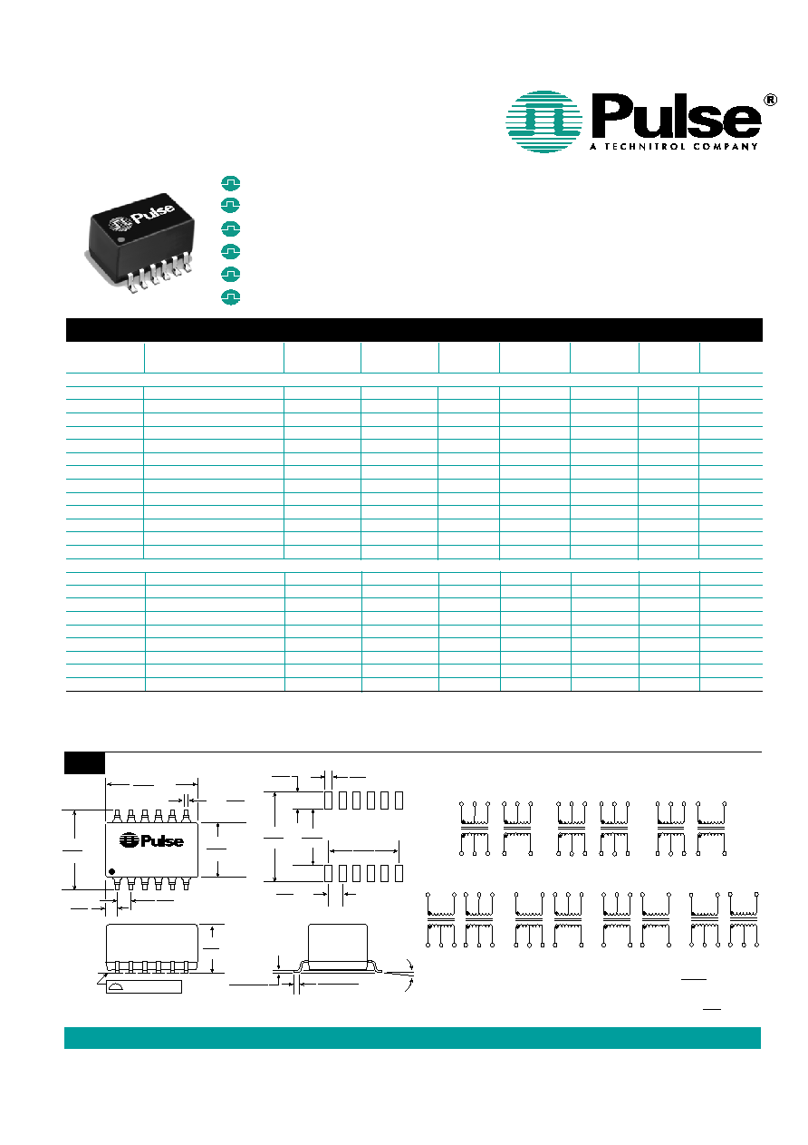
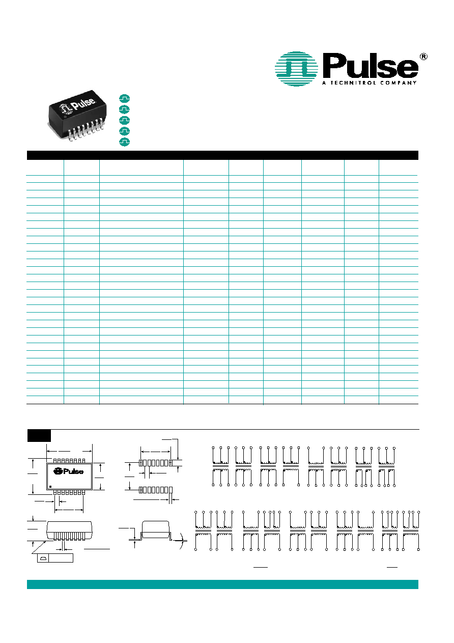
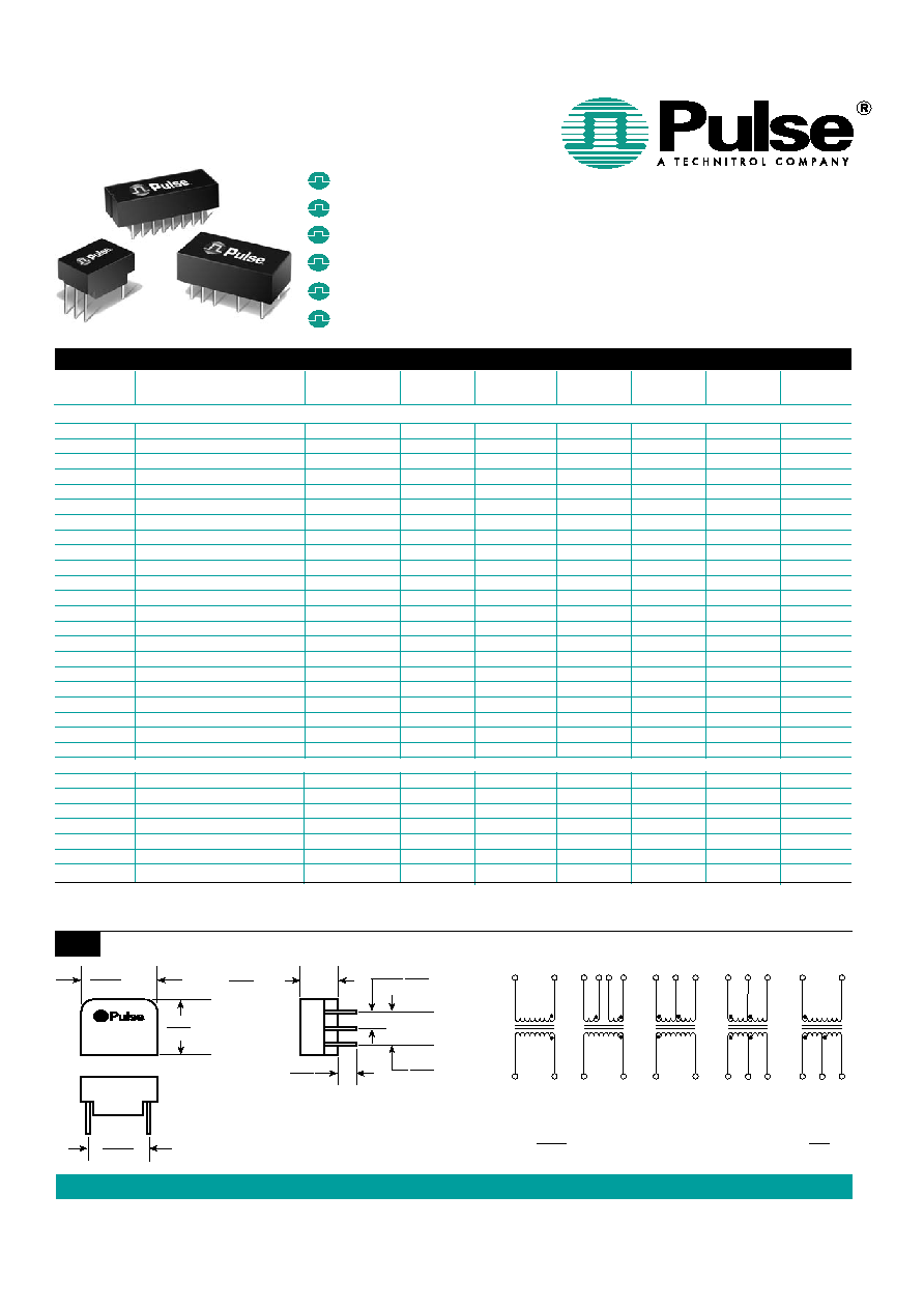
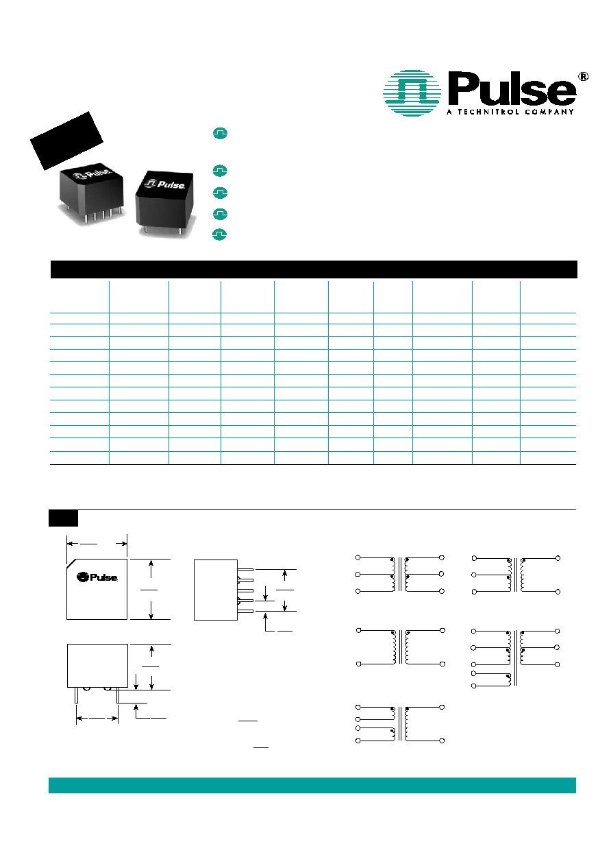
T1/CEPT/ISDN-PRI TRANSFORMERS
Single Reinforced Insulation, 3 KVrms
Certified for reinforced insulation per
EN 41003/EN 60950, UL 1459 and UL 1950
For T1/CEPT line interfaces
Matched to leading transceiver ICs
Designed to meet ITU-T G.703
Lead-Free versions available upon request
Electrical Specifications @ 25∞C -- Operating Temperature 0∞C to 70∞C (Unless Otherwise Noted)
Mechanical
Schematics
1
2
5
3
1
5
10
6
3
10
6
1
3
2
8
5
4
10
6
1
5
10
6
1
5
4
2
4
10
6
1
5
3
8
1
2
4
5
10
9
7
6
PE-XXXXX
DATE CODE
.560 MAX
14,22
.400
10,20
3
8
.560
MAX
14,22
.400 MAX
10,20
Notes:
Leads are 22 AWG solderable.
Unused pins not provided.
.130
3,30
.100 TYP
2,54
.400
10,20
Weight . . . . . . . . . . 4 grams
Tube . . . . . . . . . . . . .35/tube
(See Pages 6 and 7 for Table Notes)
Dimensions: Inches
mm
Unless otherwise specified,
all tolerances are ± .010
0,25
DCR
DCR
Safety
Turns Ratio
B
OCL
B
C
W/W
L
L
Pri
Sec
Agency
Package/
Primary
Part Number
(± 5%)
(mH MIN)
(pF MAX)
(µH MAX)
(
MAX)
(
MAX)
Recognition
10
Schematic
Pins
PE-65830
1.27CS:1
.800
15
0.70
0.50
0.35
C,T,U,B
IS/3
1-5
PE-65831
1CS:1
.800
15
0.70
0.50
0.45
C,T,U,B
IS/3
1-5
PE-65832
1:1.36CT
1.20
35
0.60
0.70
0.90
C,T,U,B
IS/4
10-6
PE-65833
A
1CT:2CT
1.20
20
0.30-0.55
0.50
0.90
C,T,U,B
IS/1
1-5
PE-65834
1:1
1.20
20
0.50
0.50
0.50
C,T,U,B
IS/2
1-5
PE-65835
1CT:2CT
1.20
15
0.80
0.70
1.10
C,T,U,B
IS/1
1-5
PE-65836
1CT:3CT:1
.600
30
0.80
0.70
1.70
C,T,U,B
IS/5
1-3
PE-65837
E
1:1.08/1.36
1.50
20
0.60
0.70
0.90
C,T,U,B
IS/4
10-6
PE-65838
1:1.14CT
1.50
30
1.00
0.70
0.90
C,T,U,B
IS/4
10-6
PE-65839
E
1:1/1.26
1.50
35
0.60
0.70
1.10
C,T,U,B
IS/4
10-6
PE-68646
E
1:1.58/2
1.50
20
0.70
0.70
1.20
C,T,U,B
IS/4
10-6
PE-68788
1CT:1.41CT
1.20
20
0.80
0.60
0.80
T,U,B
IS/1
10-6
REINFORCED
INSULATION!
3
T608.R (11/04)
IS
NOTE: For surface mount dual version with reinforced insulation products, refer to data sheet T617.

US 858 674 8100
∑
∑
UK 44 1483 401 700
∑
∑
France 33 3 84 35 04 04
∑
∑
Singapore 65 6287 8998
∑
∑
Taiwan 886 2 2698 0228
∑
∑
Hong Kong 852 2788 6588
∑
∑
http://www.pulseeng.com
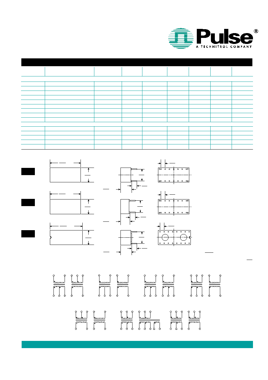
T1/CEPT/ISDN-PRI TRANSFORMERS
Application Notes
NOTES FROM TABLES (pages 1 through 6):
A. Toleranced leakage inductance: .30 µH min to .55 µH MAX.
B. OCL (primary inductance) and LL (leakage inductance) are
measured at the primary winding. Turns ratio is specified
primary: secondary. (CT = Center Tap; CS = Split Center
Tap).
C. To make a 1CT:1 ratio from a 1CT:2CT ratio, use only one
half of the secondary (2CT) winding.
D. For Reinforced 3kVrms Dual SMT Transformers, refer to
data sheet T617. For Quad SMT Transformers refer to data
sheet T615. For Octal SMT Transformers refer to data
sheet T622.
E. Dual Ratio Transformers -- These transformers have
tapped secondary windings to provide two turns ratios
(T/R). Use the entire primary winding and connect the sec-
ondary pins listed below to obtain the desired turns ratio:
Part
Turns Secondary Turns Secondary
Number
Ratio 1
Pins
Ratio 2
Pins
PE-65837
1:1.08
3-5
1:1.36
1
-
5
PE-65839
1:1
3-5
1:1.26
1
-
5
PE-65866
1:1
2-3
1:1.26
1
-
3
PE-68646
1:1.58
3-5
1:2
1
-
5
PE-65389
1:1
3-5
1:1.26
1
-
5
PE-65566
1:1
2-3
1:1.26
1
-
3
PE-65568
1:1
2-3
1:1.26
1
-
3
PE-68866
1:1
2-3
1:1.26
1
-
3
PE-68826
1:1
2-3
1:1.26
1
-
3
PE-68664
1:1
3-5
1:1.26
1
-
5
PE-68836
1:1
2-3/5-6
1:1.26
1-3/4-6
F. Standard packaging for surface mount "AN" and "LA" pack-
ages is anti-static tubes. Optional tray packaging can be
ordered by adding "R" suffix to the part number, (i.e. PE-
65857R). Optional Tape & Reel packaging can be ordered
by adding "T" suffix to the part number, (i.e. PE-65857T).
G. PE-64931 and PE-65351 are electrically equivalent, but
have different schematics. PE-65351 is both UL 1459 and
BABT recognized and is recommended for new designs
because the 3S schematic provides greater physical sepa-
ration between the primary and secondary pins.
H. PE-68618 and PE-64950: The fault locate winding is (7-8).
I. Safety Agency approvals pending.
J. The turns ratio of these devices have been designed, in
conjunction with semiconductor vendor recommendations,
to allow connections to various terminations (e.g. 75 or 120
with the same transformer). For example T1075 can be
used with the Siemens PEB 2235 to achieve connection to
the 75 or 120
cable. For 75
termination, the PEB 2235
requires the following turns ratio: 1:1.57 (Tx) and 1:1.26
(Rx) which can be achieved using pins (1-2):(15-16) for Tx
and (10-11):(5-8) for Rx. For 120
, the following turns
ratio are required: 1:2 (Tx) and 1:1 (Rx), which are pins (1-
2):(16-14) for Tx and (9-11):(5-8) for Rx on the T1075.
1. Extended Temperature Range Models -- For extended temperature range
transformers (-40∞C to +85∞C operating temperature range), OCL (Open
Circuit Inductance for the primary winding) is specified at both -40∞C and
+25∞C. At -40∞C, OCL is 600 µH minimum for all low temperature models with
the exception of PE-68827 which is 800 µH minimum and PE-65836 which is
300 µH minimum. All other parameters are specified at +25∞C only. Standard
temperature range is 0∞C to +70∞C.
2. ET Product -- All coils have an ET product of 10 V-µsec minimum.
3. Flammability -- Materials used in the products are recognized
as UL94-VO approved. Products meet the requirements of IEC 695-2-2
(Needle Flame Test).
4. Balance Characteristics -- The transformers meet the requirements for lon-
gitudinal balance of FCC part 68.
5. Common Mode Rejection Ratio -- the CMRR for all transformers is better
than 50 dB at 1 MHz. A typical test circuit is shown below.
6. Crosstalk Attenuation -- In the dual packages, which contain transmit and
receive transformers side by side, sufficient crosstalk attenuation is achieved
by the inherent characteristics of the toroid cores as well as by their proper
positioning. The crosstalk attenuation is typically 50 dB or better from 100
KHz to 10 MHz. This result was established with the test circuit shown below.
7. Return Loss -- ITU-T G.703 and European national regulatory documents
specify minimum return loss levels. The transformers will allow these limits to
be complied within the situations where they are applicable.
Frequency
50-100 KHz
100 KHz-2 MHz
2-3 MHz
Return Loss
XMIT
9 dB
15 dB
11 dB
REC
12 dB
18 dB
14 dB
8. Surge Voltage Capability ≠ All transformers and chokes
meet surge voltage tests according to the most stringent
regulatory documents when system designs include the proper voltage and
current suppression devices:
Metallic Voltage:
800 V peak, 10/560 µsec
Longitudinal Voltage:
2,400 V peak, 10/700 µsec
9.
Isolation Voltage -- 100% of transformers are tested during
production to the specified isolation voltage level.
10. Safety Agency Recognition -- Parts listed as "Recognized" or "Certified"
meet Underwriter Laboratories, UL 1459 and UL 1950 per file E133523 (S).
British Approvals Board for Telecommunications
BABT BS 6301:1989/BS 415 and BS EN 41003:1991/EN 60 950, supple-
mentary insulation.
CR/0091
PE-64933
PE-65351
PE-65558
PE-68600
PE-64934
PE-65363
PE-65586
PE-68644
PE-64936
PE-65379
PE-65755
PE-68645
PE-64937
PE-65388
PE-65770
PE-68664
PE-64943
PE-65389
PE-65771
PE-65340
PE-65415
PE-65778
Transformers with Reinforced Insulation according to IEC950 series
PE-68630--PE-68788 (page 3) are certified by the
following organizations:
Code
Certificate Information
C
CSA, C22.2 #950 & #225, Cert. LR 76802-3, reinforced insulation.
T
TÐV, EN 60 950/EN 41003, Cert. R9371358, reinforced insulation.
U
UL 1459/UL1950, File E133523 (S), reinforced insulation.
B
BABT EN41003/EN60950, Cert. CR0079, reinforced insulation.
(Note: Safety Agency approval of surface mount transformers is pending.)
11. General Information -- The transformers are specifically designed for use
in 1.544 Mbps (T1), 2.048 Mbps (CEPT) and ISDN Primary rate (PRI) inter-
face applications. They are matched to the majority of the line interface
transceiver ICs currently available. Use of the proper transformer allows the
interface circuit to comply with ITU-T G.703 and other standards regarding
pulse waveform, return loss, and balance.
12. Common Mode Chokes -- The "high-frequency" 4-lines common mode
chokes shown in this data sheet provide an effective means of compliance with
national and international regulations on EMI. They are designed to be used in
conjunction with Pulse's T1/CEPT transformers as shown in the typical appli-
cation below. Crosstalk is typically -70 dB at 1 MHz and -55 dB at 10 MHz.
HP-8751A
P1 P2
50:100
BALUN
100:50
BALUN
XFMR
50:100
BALUN
100:50
BALUN
XFMR
HP-8751A
P1 P2
100
100
IC
XMiT
Transformer
RCVE
Choke
Choke
Transformer
IC
RCVE
XMIT
Typical Application
7
T608.R (11/04)