In
-C
i
r
c
ui
t Deb
ug
g
e
r
Serial In Circuit Debugger for PIC16F87x
14330 Midway Road . Suite 128 . Dallas . Texas . 75244 Tel 972.980.2960 Fax 972.980.2937 Email: atc1@ix.netcom.com Web Site: http://www.adv-transdata.com
Copyright 1998 Advanced Transdata Corporation . Printed in USA . July 2000
SICD-87X is a low-cost development system for
Microchip's flash-based PIC16F87X microcontrollers.
Utilizing the chips' In-Circuit Debugging (ICD)
capability and Microchip's In-Circuit Programming
(ICSP) protocol, the SICD-87X is an in-circuit
debugger as well as a programmer. It runs under the
MPLAB Integrated Development Environment
which provides the front end for programming and
emulation controls like running, stepping, setting
breakpoint, etc.
Real-time code execution
In-circuit debugging
Built-in Programmer
3.0 to 5.5 volt operating range
Operates off the voltage (VDD) supplied by
the target application
Operating frequencies from 32Khz to 20Mhz
Source level and symbolic debugging
Microsoft 3.1/95/98/NT compatible
RS-232 interface
TM
Features
+
+
+
+
+
+
+
+
+
SICD-87X consists of
ICD Module
ICD Header
ICD Demo Board
9" 6-wire modular cable
The ICD Module contains all debugging, programming and control logic.
It is connected to the PC's serial port via a 9-pin serial cable and to the
ICD Header or target using a 6-wire modular cable.
The ICD Header connects the ICD Module to the circuit under test. For
in-circuit emulation, a PIC16F877 needs to be plugged into the header
which then plugs into a 28-pin or 40-pin PIC16F87X DIP socket on an
application. The Header is powered by the target application, from a 3.0
to 5.5 volt source. The modular cable can also be plugged into a modular
connector on the application for in-system programming.
The ICD Demo Board is provided for demonstration and/or evaluation of
the PIC16F87x in the absence of a customer's target application board. It
is connected to the ICD Module via the ICD Header. The PIC16F877
can be unplugged from the Header and plugged directly into the demo
board for stand-alone operation.
The demo board provides LEDs, DIP switch, push buttons, and a
potentiometer for demonstrating the chip's features. A small prototyping
area and RS232 circuitry is also available for experimentation.
The SICD-87X cannot replace a full-featured in-circuit emulator for
debugging complicated program but it does provide an inexpensive
solution to test and program the PIC16F87x.
+
+
+
+
Due to the built-in ICD and ISP functions, the SICD-87X is intrusive and
will use up the following on-chip resources: MCLR/Vpp shared for
programming; RB3 reserved for low power programming; RB6 and RB7
reserved for programming and debugging; 6 general purpose registers
(70h, 1EBh-1EFh) reserved for debug monitor; program memory
(0x1F00-0x1FFF reserved for debug code; one stack level not available.
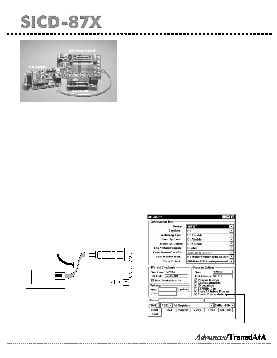
ICD Control Dialog
Un-check the "Enable Debug Mode" option to
program the chip for normal use
SICD-87X
ICD Module
16F877
ICD Demo Board
........................
........................
........................
........................
........................
........................
........................
........................
........................
Power in
T
o
RS232
ICD Header
SICD-87X Connections
ICD Module
ICD Demo Board
ICD Header