2
Dec 01, 2003
SAW Components
K 9653 D
38,90 MHz
IF Filter for Audio Applications
Data Sheet
Standard
s
B/G
s
D/K
s
I
s
M/N
Features
s
TV IF audio filter with two channels
s
Channel 1 (B/G, I, D/K) with one pass band
for sound carriers between 32,35 MHz and
33,40 MHz
s
Channel 2 (M/N) with one pass band for
sound carrier at 34,40 MHz
s
Standard IC package
Terminals
s
Tinned CuFe alloy
Duroplast package SIP5D
1
2
3
4
5
13,7
4,8
4x 2,54
0,38
3,4
2,4
0,65
Pin configuration
1
Input
2
Switching Input
3
Input - ground / Chip carrier - ground
4
Output
5
Output
Type
Ordering code
Marking and package
according to
Packing
according to
K 9653 D
B39389-K9653-N201
C61157-A1-A21
F61074-V8049-Z000
Maximum ratings
Operable temperature range
T
A
≠25/+65
∞C
Storage temperature range
T
stg
≠40/+85
∞C
DC voltage
V
DC
5
V
between any terminals
AC voltage
V
pp
10
V
between any terminals
typ. Dimensions in mm, approx. weight 0,5 g
3
Dec 01, 2003
SAW Components
K 9653 D
38,90 MHz
IF Filter for Audio Applications
Data Sheet
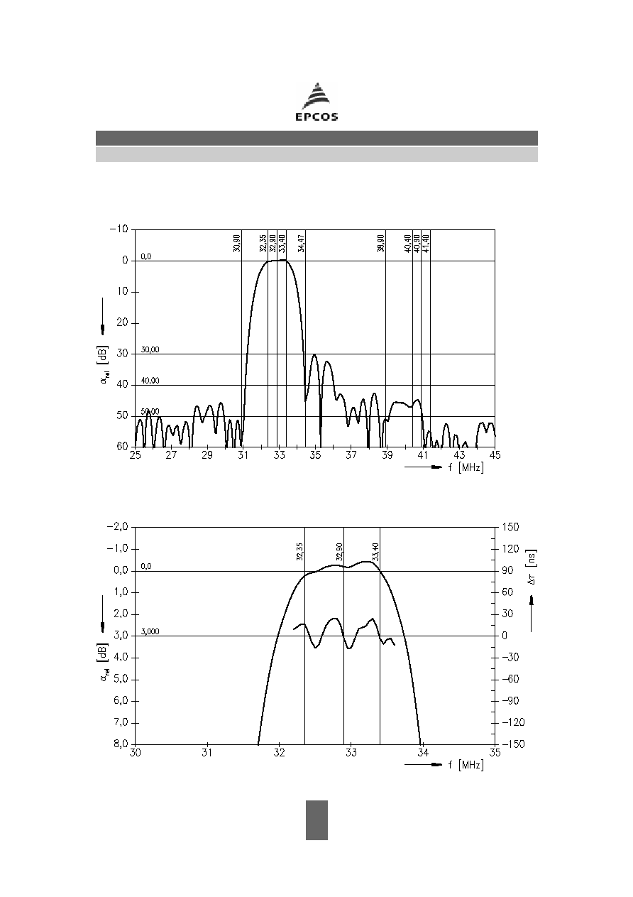
Characteristics of channel 1 (switching pin 2 connected to ground)
Reference temperature:
T
A
= 25 ∞C
Terminating source impedance:
Z
S
= 50
Terminating load impedance:
Z
L
= 2 k
|| 3 pF
min.
typ.
max.
Insertion attenuation
Reference level for the
33,40 MHz
14,7
16,2
17,7
dB
following data
Relative attenuation
rel
Sound carrier
32,35 MHz
≠0,8
0,2
1,2
dB
32,40 MHz
≠0,9
0,1
1,1
dB
32,90 MHz
≠1,3
≠0,3
0,7
dB
Picture carrier
38,90 MHz
41,0
50,0
--
dB
Color carrier
34,47 MHz
28,0
40,0
--
dB
Adjacent picture carrier
30,90 MHz
46,0
59,0
--
dB
Adjacent sound carrier
40,40 MHz
40,0
46,0
--
dB
40,90 MHz
41,0
48,0
--
dB
41,40 MHz
44,0
53,0
--
dB
Lower sidelobe
25,00 ... 30,90 MHz
40,0
45,0
--
dB
Upper sidelobe
38,90 ... 45,00 MHz
38,0
44,0
--
dB
Impedance at 33,40 MHz
Input:
Z
IN
=
R
IN
||
C
IN
--
1,2 || 8,8
--
k
|| pF
Output:
Z
OUT
=
R
OUT
||
C
OUT
--
1,0 || 7,1
--
k
|| pF
Temperature coefficient of frequency
TC
f
--
≠72
--
ppm/K

4
Dec 01, 2003
SAW Components
K 9653 D
38,90 MHz
IF Filter for Audio Applications
Data Sheet
Characteristics of channel 2 (switching pin 2 connected to pin 1)
Reference temperature:
T
A
= 25 ∞C
Terminating source impedance:
Z
S
= 50
Terminating load impedance:
Z
L
= 2 k
|| 3 pF
min.
typ.
max.
Insertion attenuation
Reference level for the
34,40 MHz
12,5
14,0
15,5
dB
following data
Relative attenuation
rel
Picture carrier
38,90 MHz
41,0
54,0
--
dB
Color carrier
35,32 MHz
25,0
34,0
--
dB
Adjacent picture carrier
32,90 MHz
33,0
48,0
--
dB
Adjacent sound carrier
40,40 MHz
41,0
50,0
--
dB
Lower sidelobe
25,00 ... 30,30 MHz
33,0
39,0
--
dB
30,30 ... 32,90 MHz
28,0
34,0
--
dB
Upper sidelobe
38,90 ... 45,00 MHz
38,0
45,0
--
dB
Impedance at 34,40 MHz
Input:
Z
IN
=
R
IN
||
C
IN
--
0,6 ||14,9
--
k
|| pF
Output:
Z
OUT
=
R
OUT
||
C
OUT
--
1,3 || 4,9
--
k
|| pF
Temperature coefficient of frequency
TC
f
--
≠72
--
ppm/K