KSI-9039-003
1
A431xM
Programmable Voltage Reference
Features
∑ Programmable output voltage to 20 volts
∑ Sink current capability of 1.0mA to 100mA
∑ Low dynamic impedance 0.15 typical
∑ Temperature compensated for operation over full rated operating temperature
∑ Equivalent full-range temperature coefficient of 50ppm/
∞C (Typical)
∑ Low output Noise voltage
Ordering
Information
Type NO.
Marking
Package Code
A431xM
A431
TO-92M
: Grade => B :±0.5% , A :±1%
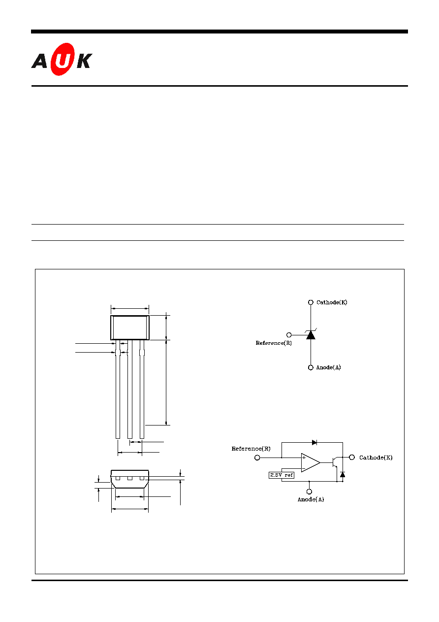
Outline Dimensions unit :
mm
S
S
e
e
m
m
i
i
c
c
o
o
n
n
d
d
u
u
c
c
t
t
o
o
r
r
Symbol
PIN Connections
1. Reference
2. Anode
3. Cathode
Functional block diagram
14.0
±
0.4
0
4.0±0.1
0.44 REF
0.52 REF
3.0
±
0.
1
1.27 Typ.
2.54±0.1.
3.0±0.1
0.
4
2
Typ.
0.
7 Typ
.
1 2 3
3.8 Min.

KSI-9039-003
2
A431xM
Absolute maximum ratings
(Operating ambient temperature range applies unless other specified)
Parameter Symbol
Ratings
Unit
Cathode to Anode voltage
V
KA
20 V
Cathode current range
I
KA
-100
~+150
mA
Reference input current range
I
ref
-0.05~+10
mA
Power dissipation
P
D
500
mW
Operating temperature range
T
opr
-40~+85
∞C
Storage temperature range
T
stg
-65~+150
∞C
Recommended operating conditions
Ratings
Parameter Symbol
Min. Max.
Unit
Cathode to Anode voltage
V
KA
V
ref
18 V
Cathode current range
I
KA
1.0
100
mA
Electrical Characteristics
(Ambient temperature at 25
∞C, unless otherwise noted.)
Parameter Symbol
Condition
Min.
Typ.
Max. Unit
A431BM 2.482
2.508
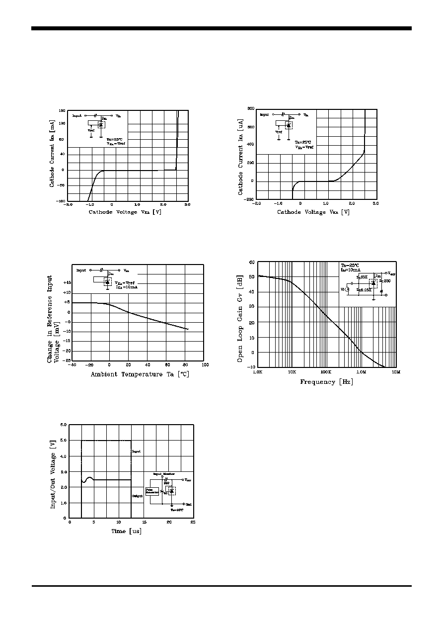
Reference input voltage
(Fig. 1, Note 1)
V
ref
V
KA
=V
ref
,
I
KA
=10mA
A431AM 2.470
2.495
2.520
V
Deviation of reference input voltage
Over temperature(Fig. 1, Note 1,2)
V
ref
V
KA
=V
ref
, I
KA
=10mA
@Ta=T
LOW
to T
HIGH
- 7.0 30 mV
Ratio of change in reference input
Voltage to the change in cathode
Voltage(Fig. 2)
V
ref
V
KA
I
KA
=10mA
V
KA
=10V-V
ref
V
KA
=20V-10V
-
-
1.2
0.7
2.7
2.0
mV/V
Reference input current(Fig. 2)
I
ref
I
KA
=10mA
R1=10K, R2=
- 1.8 4.0 µA
Deviation of reference input current
over temperature(Fig. 2)
I
ref
I
KA
=10mA
R1=10K, R2=
- 0.4 2.5 µA
Minimum cathode current for
Regulation(Fig. 1)
I
MIN
V
KA
=V
ref
-
0.35
1.0
mA
Off-state cathode current(Fig. 3)
I
OFF
V
KA
=20V, V
ref
=0V -
2.7
1000
nA
Dynamic impedance(Fig. 1, Note 3)
Z
KA
V
KA
=V
ref
, f1.0KHz
I
KA
=1.0mA-100mA
- 0.14 0.5
Fig. 1 Fig. 2 Fig. 3
<Note 1> : T
LOW
=-40
∞C, T
HIGH
=+85
∞C , <Note 2> :
V
ref
= V
ref
Max. - V
ref
Min.
, <Note 3> : Z
KA
=
V
KA
/
I
KA

KSI-9039-003
4
A431xM
These AUK products are intended for usage in general electronic equipments(Office and
communication equipment, measuring equipment, domestic electrification, etc.).
Please make sure that you consult with us before you use these AUK products in equipm-
ents which require high quality and/or reliability, and in equipments which could have
major impact to the welfare of human life(atomic energy control, airplane, spaceship, traffic
signal, combustion central, all types of safety device, etc.).
AUK cannot accept liability to any damage which may occur in case these AUK products
were used in the mentioned equipments without prior consultation with AUK.