 | –≠–ª–µ–∫—Ç—Ä–æ–Ω–Ω—ã–π –∫–æ–º–ø–æ–Ω–µ–Ω—Ç: AMT8410 | –°–∫–∞—á–∞—Ç—å:  PDF PDF  ZIP ZIP |

09/2002
V
OUT
V
OUT
V
CC
2
4
1
3
P
IN
AGC
AMT8410
2.5 Gb/s 1310/1550nm PIN-TIA
PRELIMINARY DATA SHEET - Rev 1.1
TO-46L
TO-46 Ball Lens Package
FEATURES
∑
2.5 Gb/s Differential Output TIA
∑
3.3 V Operation
∑
Automatic Gain Control
∑
55
µ
m 1270-1560 nm PIN Photodetector
∑
2000 MHz Bandwidth
∑
-23 dBm Typical Sensitivity
∑
+2 dBm Optical Overload
∑
TO-46 Lens Package
APPLICATIONS
∑
SONET OC-48/SDH STM-16 (2.488 Gb/s)
∑
2 x Fibre Channel (2.125 Gb/s)
∑
2.5 Gb/s Infiniband
PRODUCT DESCRIPTION
The ANADIGICS AMT8410, packaged in a TO46
lens can, is a 3.3 V integrated photodetector and
transimpedance amplifier (TIA) used to convert a
long wavelength (1270 to 1560 nm) input optical
signal into a differential output voltage. The
AMT8410 has a bandwidth of 2000 MHz and a
dynamic range of 25 dB. These devices are readily
designed into receivers, transceivers and
transponders for SONET, Fibre Channel and
Infiniband applications.
Figure 1: Funtional Block Diagram
2
PRELIMINARY DATA SHEET - Rev 1.1
09/2002
AMT8410
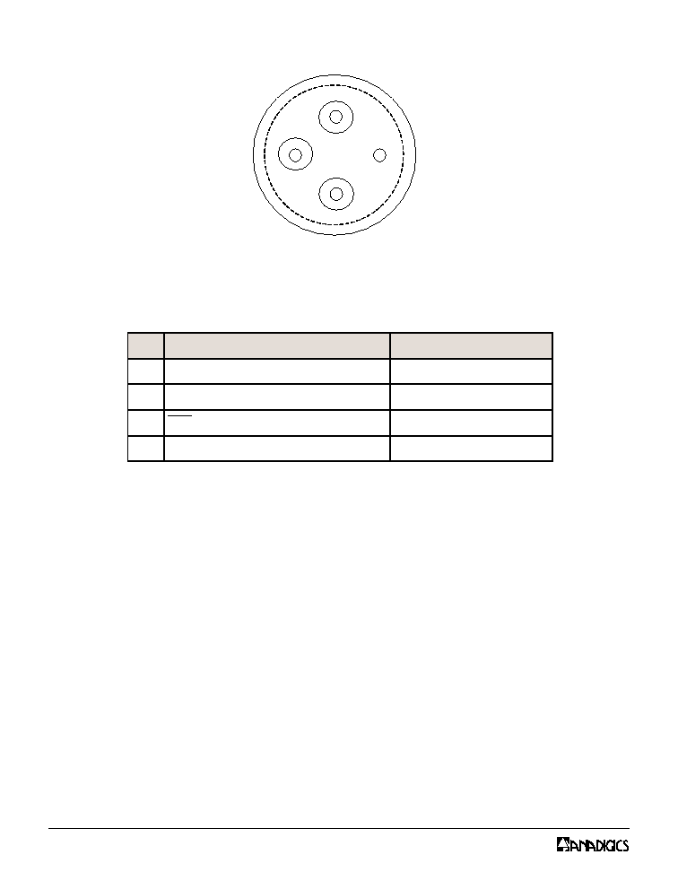
1
2
3
4
Figure 2: T46L Pinout (Bottom View)
Table 1: Pin Description
N
I
P
N
O
I
T
P
I
R
C
S
E
D
T
N
E
M
M
O
C
1
V
T
U
O
)
d
e
t
r
e
v
n
I
-
n
o
N
(
e
g
a
tl
o
V
t
u
p
t
u
O
A
I
T
-
t
u
p
n
i
l
a
c
it
p
o
h
ti
w
'
1
'
l
a
c
i
g
o
L
2
V
C
C
e
g
a
tl
o
V
y
l
p
p
u
S
e
v
it
i
s
o
P
-
s
tl
o
V
3
.
3
+
3
V
T
U
O
)
d
e
t
r
e
v
n
I
(
e
g
a
tl
o
V
t
u
p
t
u
O
A
I
T
-
t
u
p
n
i
l
a
c
it
p
o
h
ti
w
'
0
'
l
a
c
i
g
o
L
4
d
n
u
o
r
G
d
e
d
n
u
o
r
g
s
i
e
s
a
C

PRELIMINARY DATA SHEET - Rev 1.1
09/2002
AMT8410
3
ELECTRICAL CHARACTERISTICS
Table 2: Absolute Maximum Ratings
Stresses in excess of the absolute ratings may
cause permanent damage. Functional operation
is not implied under these conditions. Exposure
to absolute ratings for extended periods of time
may adversely affect reliability.
V
C
C
V
0
.
6
P
N
I
m
B
d
4
+
T
S
C
∞
5
2
1
o
t
C
∞
5
6
-
.
p
m
e
T
e
g
a
r
o
t
S
R
E
T
E
M
A
R
A
P
N
I
M
P
Y
T
X
A
M
T
I
N
U
(
h
t
g
n
e
l
e
v
a
W
)
0
7
2
1
0
0
3
1
0
6
5
1
m
n
a
e
r
A
e
v
it
c
A
r
o
t
c
e
t
e
D
-
5
5
-
µm
y
ti
v
i
s
n
o
p
s
e
R
l
a
it
n
e
r
e
ff
i
D
l
a
n
g
i
S
ll
a
m
S
)
z
H
M
0
0
1
@
(
)
1
(
0
0
7
1
0
0
0
2
-
W
/
V
h
t
d
i
w
d
n
a
B
)
1
(
0
0
7
1
0
0
0
2
-
z
H
M
ff
o
t
u
C
y
c
n
e
u
q
e
r
F
w
o
L
-
0
0
1
-
z
H
k
e
c
n
a
t
s
i
s
e
R
t
u
p
t
u
O
-
0
5
-
d
a
o
lr
e
v
O
l
a
c
it
p
O
)
2
(
0
2
+
-
m
B
d
y
ti
v
it
i
s
n
e
S
l
a
c
it
p
O
)
2
(
1
2
-
3
2
-
-
m
B
d
e
g
a
tl
o
V
t
u
p
t
u
O
l
a
it
n
e
r
e
ff
i
D
m
u
m
i
x
a
M
-
-
0
0
3
V
m
T
E
S
I
R
T
&
L
L
A
F
)
%
0
8
-
0
2
(
)
3
(
-
0
6
1
-
s
p
n
o
it
r
o
t
s
i
D
e
l
c
y
C
y
t
u
D
)
4
(
-
6
-
%
r
e
tt
i
J
l
a
t
o
T
)
5
(
,
)
4
(
-
5
4
-
s
p
t
n
e
r
r
u
C
y
l
p
p
u
S
-
5
5
0
0
1
A
m
e
g
n
a
R
e
g
a
tl
o
V
g
n
it
a
r
e
p
O
0
.
3
+
3
.
3
+
6
.
3
+
V
e
g
n
a
R
e
r
u
t
a
r
e
p
m
e
T
g
n
it
a
r
e
p
O
0
4
-
-
5
8
+
C
∞
Table 3: Electrical Specifications
Notes:
(1) Measured at -17 dBm optical input power with output connected into R
L
= 100
(differential).
(2) Measured at 10
-10
BER with a 2
23
-1 PRBS at 2.5 Gb/s.
(3) Measured with a 2
23
-1 PRBS at 2.5Gb/s, an input optical power of -17dBm and
R
L
= 100
(differential).
(4) Measured with a 2
23
-1 PRBS at 2.5Gb/s, an input optical power of -3dBm and
R
L
= 100
(differential).
(5) 6
about the center eye crossing.

4
PRELIMINARY DATA SHEET - Rev 1.1
09/2002
AMT8410
PERFORMANCE DATA
Figure 7: Differential Responsivity vs. Case
Temperature
1000
1250
1500
1750
2000
2250
2500
2750
3000
0
10
20
30
40
50
60
70
80
90
Case Temperature (C)
Differential
Responsivity
(V/W
)
3V
3.3V
3.6V
-25.00
-24.50
-24.00
-23.50
-23.00
-22.50
-22.00
-21.50
-21.00
0
10
20
30
40
50
60
70
80
90
Case Temperature (C)
S
e
n
s
it
iv
it
y
(
d
B
m
)
3V
3.3V
3.6V
Figure 8: Sensitivity vs. Case Temperature
40.0
45.0
50.0
55.0
60.0
65.0
70.0
75.0
80.0
0
10
20
30
40
50
60
70
80
90
Case Temperature (C)
Supply
Current
(mA)
Pin
=
-17dBm
3V
3.3V
3.6V
Figure 5: Supply Current vs. Case Temperature
Figure 6: Bandwidth vs. Case Temperature
1600
1700
1800
1900
2000
2100
2200
2300
2400
0
10
20
30
40
50
60
70
80
90
Case Temperature (C)
Bandwidth
(MHz)
3V
3.3V
3.6V
Figure 3: Eye Diagram with an Optical Input
Power of -23 dBm
100 ps/Div.
5 mV/Div.
Figure 4: Eye Diagram with an Optical Input
Power of -15 dBm
100 ps/Div.
25 mV/Div.
PRELIMINARY DATA SHEET - Rev 1.1
09/2002
AMT8410
5
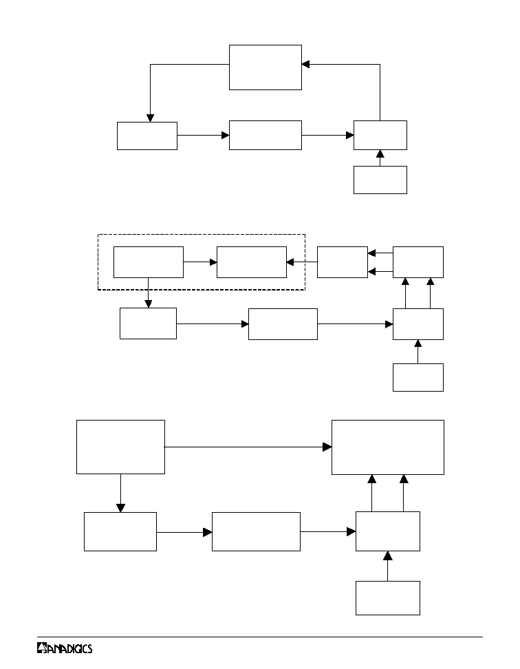
Lightwave
Analyzer
HP 8702D
Laser
Optical
Attenuator
DUT Test
Fixture
Power
Supply
Extinction
Ratio = 3 dB
MEASUREMENT METHODS
Pulse Pattern
Generator
Laser
Optical
Attenuator
DUT Test
Fixture
Power
Supply
Digital
Communication
Analyser
HP83480A
Extinction
Ratio = 9 dB
Figure 11: Test Setup for Eye Measurements
Figure 10: Test Setup for Sensitivity Measurements
Figure 9: Test Setup for Frequency Measurements
Extinction
Ratio >9 dB
BERT
Pulse Pattern
Generator
Laser
Limiting
Amplifier
Hybrid
Coupler
Error Detector
Power
Supply
Optical
Attenuator
DUT Test
Fixture