AMT8210
1.25 Gb/s 1310/1550nm PIN-TIA
FEATURES
∑
1.25 Gb/s differential output TIA
∑
DC to 1000 MHz bandwidth
∑
+3.3V Operation
∑
-27dBm Typical sensitivity
∑
1250-1620nm PIN Photodetector
∑
Automatic Gain Control (AGC)
∑
0dBm Optical Overload
APPLICATIONS
∑
Gigabit Ethernet (1.25 Gb/s)
∑
Fiber Channel (1.0625 Gb/s)
∑
FTTx systems
TO-46 4 pin Ball
Lens Package
TO-46 5 pin Ball
Lens Package
Product Description
The ANADIGICS AMT8210, packaged in a TO46
lens can, is a 3.3V integrated photodetector and
transimpedance amplifier (TIA) used to convert a
long wavelength (1250 to 1620nm) optical input
signal into a differential output voltage. The
AMT8210 has a bandwidth of 900MHz and a
dynamic range of over 27dB. These devices are
readily designed into receivers, transceivers and
transponders for Gigabit Ethernet and Fiber
Channel applications.
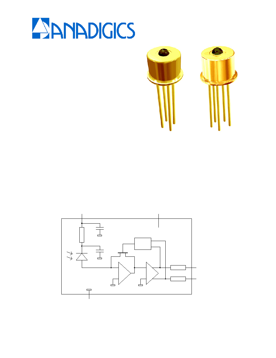
AGC
OUT
OUTQ
GND
VCC
VPD
(For the 4 pin header VPD and VCC are connected to the same pin)
Figure 1: Functional Block Diagram

AMT8210
Rev 1.1
2
ELECTRICAL CHARACTERISTICS
Table 1: Absolute Maximum Ratings
PARAMETER
MIN
MAX
UNIT
Supply Voltage
-0.5
+3.8
V
Optical Input Power
-
+ 3
dBm
Storage Temperature
- 40
+ 125
oC
Stresses in excess of the absolute ratings may cause permanent damage. Functional
operation is not implied under these conditions. Exposure to absolute ratings for extended
periods of time may adversely affect reliability.
Table 2: Electrical Specifications
PARAMETER
MIN
TYP
MAX
UNIT
Wavelength 1250
-
1620
nm
Detector Active Area
-
75
-
um
Sensitivity
(1)
-25.0 -27 - dB
Overload
0
-
dBm
Responsivity 1550nm
-
0.95
-
A/W
Responsivity 1310nm
-
0.85
-
A/W
Small signal transimpedance gain (50
)
- 9.1 - K
Small signal 3dB bandwidth
800
1000
-
MHz
Output resistance
50
Output voltage swing (differential)
500
mV
P-P
TIA supply voltage
2.97
3.3
3.6
V
TIA supply current
-
21
mA
Power consumption
-
70
mW
Operating temperature -40
+25
+85
oC
(1) 1.25Gb/s PRBS 2
31
-1, 1550nm, ER >12dB, BER 10
-10
Figure 2: Pin location (4-pin)
OUTQ
OUT
VCC
GND
(Bottom View)
Figure 3: Pin location (5-pin)
VCC
OUTQ
GND
OUT
VPD
(Bottom View)
Table 3: Pin description
NAME
DESCRIPTION
OUT
TIA Output (Non-Inverted)
VCC
Supply Voltage (+3.3V)
OUTQ
TIA Output (Inverted)
GND Ground

AMT8210
Rev 1.1
3
PACKAGE DIMENSIONS ≠ 5 Pin TO-46

AMT8210
Rev 1.1
4
PACKAGE DIMENSIONS ≠ 4 Pin TO-46
ORDERING INFORMATION
Part Number
PACKAGE DESCRIPTION
AMT8210T46L4
4 pin TO-46 Lens Package
AMT8210T46L5
5 pin TO-46 Lens Package
ANADIGICS, Inc.
829 Flynn Road
Camarillo, California 93012, U.S.A.
Tel: +1 (805) 445-4500
Fax: +1 (805) 445-4502
URL:
http://www.anadigics.com
E-mail: Mktg@anadigics.com
IMPORTANT NOTICE
ANADIGICS, Inc. reserves the right to make changes to its products or discontinue any product at any
time without notice. The product specifications contained in Advanced Product Information sheets and
Preliminary Data sheets are subject to change prior to a product's formal introduction. Information in
Data Sheets have been carefully checked and are assumed to be reliable; however, ANADIGICS
assumes no responsibility for inaccuracies. ANADIGICS strongly urges customers to verify that the
information they are using is current before placing orders.
WARNING
ANADIGICS products are not intended for use in life support appliances, devices, or systems. Use of
an ANADIGICS product in any such application without written consent is prohibited.