Äîêóìåíòàöèÿ è îïèñàíèÿ www.docs.chipfind.ru

PRELIMINARY
This Data Sheet states AMD's current technical specifications regarding the Product described herein. This Data
Sheet may be revised by subsequent versions or modifications due to changes in technical specifications.
Publication# 23709
Rev: A Amendment/+3
Issue Date: December 21, 2000
Refer to AMD's Website (www.amd.com) for the latest information.
Am29BDS643D
64 Megabit (4 M x 16-Bit)
CMOS 1.8 Volt-only Simultaneous Read/Write, Burst Mode Flash Memory
DISTINCTIVE CHARACTERISTICS
s
Single 1.8 volt read, program and erase (1.7 to
1.9 volt)
s
Multiplexed Data and Address for reduced I/O
count
-- A0A15 multiplexed as D0D15
-- Addresses are latched with AVD# control inputs
while CE# low
s
Simultaneous Read/Write operation
-- Data can be continuously read from one bank
while executing erase/program functions in other
bank
-- Zero latency between read and write operations
s
Read access times at 54 MHz/40 MHz
-- Burst access times of 13.5/20 ns @ 30 pF
at industrial temperature range
-- Asynchronous random access times
of 90/90 ns @ 30 pF
-- Synchronous random access times
of 106/120 ns @ 30 pF
s
Burst length
-- Continuous linear burst
s
Power dissipation (typical values, 8 bits
switching, C
L
= 30 pF)
-- Burst Mode Read: 25 mA
-- Simultaneous Operation: 40 mA
-- Program/Erase: 15 mA
-- Standby mode: 0.2 µA
s
Sector Architecture
-- Eight 4 Kword sectors and one hundred
twenty-seven 32 Kword sectors
-- Bank A contains the eight 4 Kword sectors and
thirty-one 32 Kword sectors
-- Bank B contains ninety-six 32 Kword sectors
s
Sector Protection
-- Software command sector locking
-- WP# protects the last two boot sectors
-- All sectors locked when V
PP
= V
IL
s
Handshaking feature
-- Provides host system with minimum possible
latency by monitoring RDY
s
Software command set compatible with JEDEC
42.4 standards
-- Backwards compatible with Am29F and Am29LV
families
s
Minimum 1 million erase cycle guarantee
per sector
s
20-year data retention at 125
°
C
-- Reliable operation for the life of the system
s
Embedded Algorithms
-- Embedded Erase algorithm automatically
preprograms and erases the entire chip or any
combination of designated sectors
-- Embedded Program algorithm automatically
writes and verifies data at specified addresses
s
Data# Polling and toggle bits
-- Provides a software method of detecting
program and erase operation completion
s
Erase Suspend/Resume
-- Suspends an erase operation to read data from,
or program data to, a sector that is not being
erased, then resumes the erase operation
s
Hardware reset input (RESET#)
-- Hardware method to reset the device for reading
array data
s
CMOS compatible inputs, CMOS compatible
outputs
s
Low V
CC
write inhibit
s
48-Ball FBGA package
2
Am29BDS643D
P R E L I M I N A R Y
GENERAL DESCRIPTION
The Am29BDS643 is a 64 Mbit, 1.8 Volt-only, simulta-
neous Read/Write, Burst Mode Flash memory device,
organized as 4,194,304 words of 16 bits each. This
device uses a single V
CC
of 1.7 to 1.9 V to read, pro-
gram, and erase the memory array. A 12.0-volt V
PP
may be used for faster program performance if desired.
The device can also be programmed in standard
EPROM programmers.
At 40 MHz, the Am29BDS643 provides a burst access
of 20 ns at 30 pF with initial access times of 120 ns at
30 pF. At 54 MHz, the Am29BDS643 provides a burst
access of 13.5 ns at 30 pF with initial access times of
106 ns at 30 pF. The device operates within the indus-
trial temperature range of 40
°
C to +85
°
C. The device
is offered in the 48-ball FBGA package.
Simultaneous Read/Write Operations with
Zero Latency
The Simultaneous Read/Write architecture provides
simultaneous operation by dividing the memory
space into two banks. The device can improve overall
system performance by allowing a host system to pro-
gram or erase in one bank, then immediately and si-
multaneously read from the other bank, with zero
latency. This releases the system from waiting for the
completion of program or erase operations.
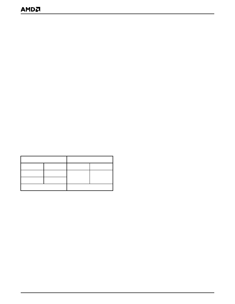
The device is divided as shown in the following table:
The device uses Chip Enable (CE#), Write Enable
(WE#), Address Valid (AVD#) and Output Enable
(OE#) to control asynchronous read and write opera-
tions. For burst operations, the device additionally
requires Power Saving (PS), Ready (RDY), and Clock
(CLK). This implementation allows easy interface with
minimal glue logic to a wide range of microproces-
sors/microcontrollers for high performance read opera-
tions.
The device offers complete compatibility with the
JEDEC 42.4 single-power-supply Flash command
set standard. Commands are written to the command
register using standard microprocessor write timings.
Reading data out of the device is similar to reading
from other Flash or EPROM devices.
The host system can detect whether a program or
erase operation is complete by using the device sta-
tus bit DQ7 (Data# Polling) and DQ6/DQ2 (toggle
bits). After a program or erase cycle has been com-
pleted, the device automatically returns to reading
array data.
The sector erase architecture allows memory sec-
tors to be erased and reprogrammed without affecting
the data contents of other sectors. The device is fully
erased when shipped from the factory.
Hardware data protection measures include a low
V
CC
detector that automatically inhibits write opera-
tions during power transitions. The device also offers
three types of data protection at the sector level. The
sector lock/unlock command sequence disables or
re-enables both program and erase operations in any
sector. When at V
IL
, WP# locks the two outermost sec-
tors. Finally, when V
PP
is at V
IL
, all sectors are locked.
The device offers two power-saving features. When
addresses have been stable for a specified amount of
time, the device enters the automatic sleep mode.
Th e system can also place the device into the
standby mode. Power consumption is greatly re-
duced in both modes.
Bank A Sectors
Bank B Sectors
Quantity
Size
Quantity
Size
8
4 Kwords
96
32 Kwords
31
32 Kwords
16 Mbits total
48 Mbits total

Am29BDS643D
3
P R E L I M I N A R Y
TABLE OF CONTENTS
Product Selector Guide . . . . . . . . . . . . . . . . . . . . . 4
Block Diagram . . . . . . . . . . . . . . . . . . . . . . . . . . . . 4
Block Diagram of
Simultaneous Operation Circuit . . . . . . . . . . . . . . 5
Connection Diagram . . . . . . . . . . . . . . . . . . . . . . . . 6
Special Handling Instructions for FBGA Package .................... 6
Input/Output Descriptions . . . . . . . . . . . . . . . . . . . 7
Logic Symbol . . . . . . . . . . . . . . . . . . . . . . . . . . . . . 7
Ordering Information . . . . . . . . . . . . . . . . . . . . . . . 8
Device Bus Operations . . . . . . . . . . . . . . . . . . . . . . 9
Table 1. Device Bus Operations ......................................................9
Requirements for Asynchronous Read Operation (Non-Burst) 9
Requirements for Synchronous (Burst) Read Operation .......... 9
Programmable Wait State ...................................................... 10
Handshaking ........................................................................... 10
Power Saving Function ........................................................... 10
Simultaneous Read/Write Operations with Zero Latency ....... 10
Writing Commands/Command Sequences ............................ 10
Accelerated Program Operation ............................................. 11
Autoselect Functions .............................................................. 11
Automatic Sleep Mode ........................................................... 11
RESET#: Hardware Reset Input ............................................. 11
Output Disable Mode .............................................................. 11
Hardware Data Protection ...................................................... 12
Low VCC Write Inhibit ............................................................ 12
Write Pulse "Glitch" Protection ............................................... 12
Logical Inhibit .......................................................................... 12
Table 2. Sector Address Table ........................................................13
Command Definitions . . . . . . . . . . . . . . . . . . . . . . 17
Reading Array Data ................................................................ 17
Set Wait State Command Sequence ...................................... 17
Table 3. Third Cycle Address/Data .................................................17
Handshaking ........................................................................... 17
Enable PS (Power Saving) Mode Command Sequence ........ 17
Sector Lock/Unlock Command Sequence .............................. 17
Reset Command ..................................................................... 18
Autoselect Command Sequence ............................................ 18
Program Command Sequence ............................................... 18
Unlock Bypass Command Sequence ..................................... 18
Figure 1. Program Operation .......................................................... 19
Chip Erase Command Sequence ........................................... 19
Sector Erase Command Sequence ........................................ 20
Erase Suspend/Erase Resume Commands ........................... 20
Figure 2. Erase Operation............................................................... 21
Command Definitions ............................................................. 22
Table 4. Command Definitions .......................................................22
Write Operation Status . . . . . . . . . . . . . . . . . . . . . 23
DQ7: Data# Polling ................................................................. 23
Figure 3. Data# Polling Algorithm .................................................. 23
DQ6: Toggle Bit I .................................................................... 24
Figure 4. Toggle Bit Algorithm........................................................ 24
DQ2: Toggle Bit II ................................................................... 25
Table 5. DQ6 and DQ2 Indications ................................................ 25
Reading Toggle Bits DQ6/DQ2 ............................................... 25
DQ5: Exceeded Timing Limits ................................................ 25
DQ3: Sector Erase Timer ....................................................... 26
Table 6. Write Operation Status ..................................................... 26
Absolute Maximum Ratings. . . . . . . . . . . . . . . . . 27
Figure 5. Maximum Negative Overshoot Waveform ...................... 27
Figure 6. Maximum Positive Overshoot Waveform........................ 27
Operating Ranges . . . . . . . . . . . . . . . . . . . . . . . . . 27
DC Characteristics . . . . . . . . . . . . . . . . . . . . . . . . 28
Test Conditions. . . . . . . . . . . . . . . . . . . . . . . . . . . 29
Figure 7. Test Setup....................................................................... 29
Table 7. Test Specifications ........................................................... 29
Key to Switching Waveforms. . . . . . . . . . . . . . . . 29
Switching Waveforms. . . . . . . . . . . . . . . . . . . . . . 29
Figure 8. Input Waveforms and Measurement Levels ................... 29
AC Characteristics . . . . . . . . . . . . . . . . . . . . . . . . 30
Synchronous/Burst Read ........................................................ 30
Figure 9. Burst Mode Read (54 MHz) ............................................ 30
Figure 10. Burst Mode Read (40 MHz) .......................................... 31
Asynchronous Read ............................................................... 32
Figure 11. Asynchronous Mode Read............................................ 32
Figure 12. Reset Timings ............................................................... 33
Erase/Program Operations ..................................................... 34
Figure 13. Program Operation Timings.......................................... 35
Figure 14. Chip/Sector Erase Operations ...................................... 36
Figure 15. Accelerated Unlock Bypass Programming Timing........ 37
Figure 16. Data# Polling Timings (During Embedded Algorithm) .. 38
Figure 17. Toggle Bit Timings (During Embedded Algorithm)........ 38
Figure 18. Latency with Boundary Crossing .................................. 39
Figure 19. Initial Access with Power Saving (PS)
Function and Address Boundary Latency ...................................... 40
Figure 20. Example of Five Wait States Insertion
(Non-Handshaking Device) ............................................................ 41
Figure 21. Back-to-Back Read/Write Cycle Timings ...................... 42
Erase and Programming Performance . . . . . . . 43
Data Retention. . . . . . . . . . . . . . . . . . . . . . . . . . . . 43
Physical Dimensions* . . . . . . . . . . . . . . . . . . . . . 44
FDE048--48-Pin Fine-Pitch Ball Grid Array (FBGA)
11 x 10 mm package ............................................................. 44
Revision Summary . . . . . . . . . . . . . . . . . . . . . . . . 46
Revision A (June 20, 2000) .................................................... 46
Revision A+1 (November 27, 2000) ....................................... 46
Revision A+2 (November 30, 2000) ....................................... 46
Revision A+3 (December 21, 2000) ....................................... 46
4
Am29BDS643D
P R E L I M I N A R Y
PRODUCT SELECTOR GUIDE
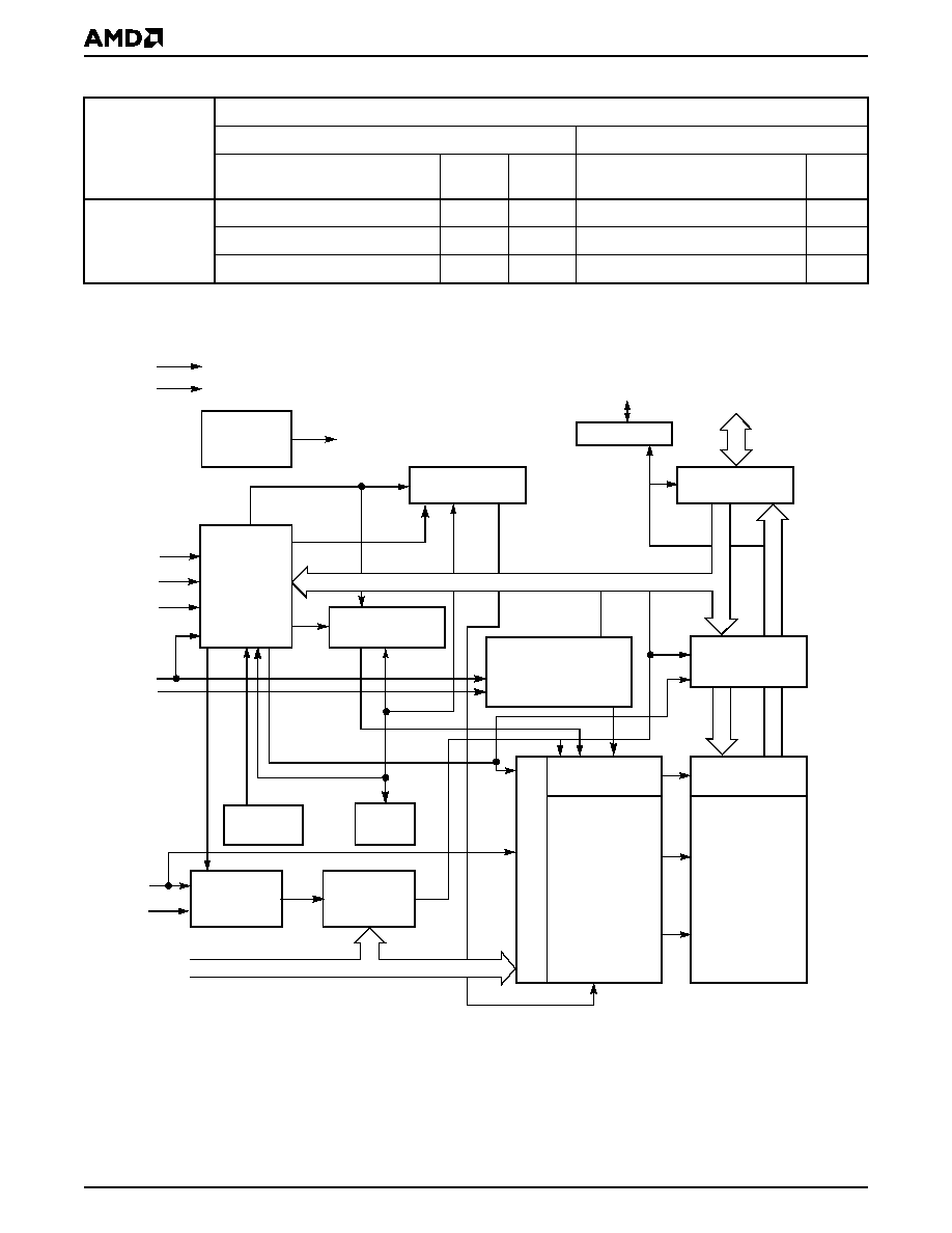
BLOCK DIAGRAM
Part Number
Am29BDS643D
Synchronous/Burst
Asynchronous
Speed Option
9A
(40 MHz)
9B
(54 MHz)
Speed Option
9A,
9B
V
CC
= 1.7 1.9 V
Max Initial Access Time, ns (t
IACC
)
120
106
Max Access Time, ns (t
ACC
)
90
Max Burst Access Time, ns (t
BACC
)
20
13.5
Max CE# Access, ns (t
CE
)
90
Max OE# Access, ns (t
OE
)
20
20
Max OE# Access, ns (t
OE
)
35
Input/Output
Buffers
X-Decoder
Y-Decoder
Chip Enable
Output Enable
Logic
Erase Voltage
Generator
PGM Voltage
Generator
Timer
V
CC
Detector
State
Control
Command
Register
V
CC
V
SS
WE#
RESET#
V
PP
CE#
OE#
A/DQ0
A/DQ15
Data
Latch
Y-Gating
Cell Matrix
Add
r
es
s Latc
h
A/DQ0A/DQ15
A16A21
RDY
Buffer
RDY
Burst
State
Control
Burst
Address
Counter
PS Buffer
PS
AVD#
CLK
A0A21
Am29BDS643D
5
P R E L I M I N A R Y
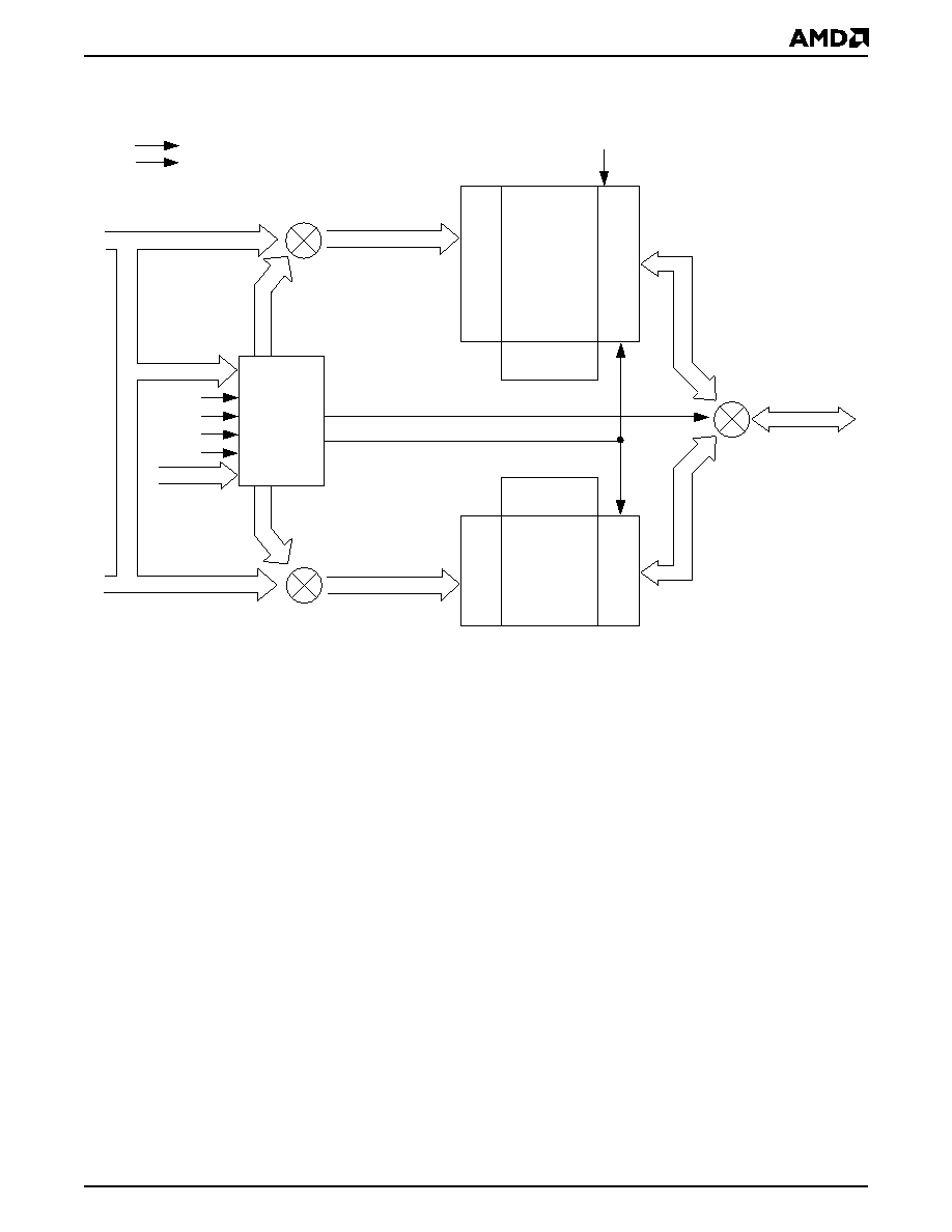
BLOCK DIAGRAM OF
SIMULTANEOUS OPERATION CIRCUIT
Note: A0A15 are multiplexed with DQ0DQ15.
V
CC
V
SS
Upper Bank Address
A0A21
RESET#
WE#
CE#
AVD#
DQ0DQ15
STATE
CONTROL
&
COMMAND
REGISTER
Upper Bank
X-Decoder
Y-Decoder
Latches and Control Logic
OE#
DQ0DQ15
Lower Bank
Y-Decoder
X-Decoder
Latches and
Control Logic
Lower Bank Address
Status
Control
A0A21
A0A21
A0A21
A0A21
DQ0DQ15
DQ0DQ15
Document Outline