Document Outline
- BitBlaster Serial Download Cable Data Sheet

Æ
Altera Corporation
1
BitBlaster
Serial Download Cable
February 2002, ver. 4.3
Data Sheet
DS-BITBL-4.3
De
vel
o
p
m
en
t
13
To
o
l
s
Features
Allows PC and UNIX workstation users to perform the following
functions:
≠
Program MAX
Æ
9000, MAX 7000S, MAX 7000A, and
MAX 3000A devices in-system via a standard RS-232 serial port
≠
Configure FLEX
Æ
10K, FLEX 8000, and FLEX 6000 devices
in-circuit via a standard RS-232 serial port
Downloads data from:
≠
MAX+PLUS
Æ
II development software on PCs and UNIX
workstations
≠
A system prompt on PCs and UNIX workstations
Provides two data download modes: passive serial (PS) and JTAG
Programs/configures a single device or multiple devices in a chain
Supports data transfer rates from 9,600 to 230,400 baud
Functional
Description
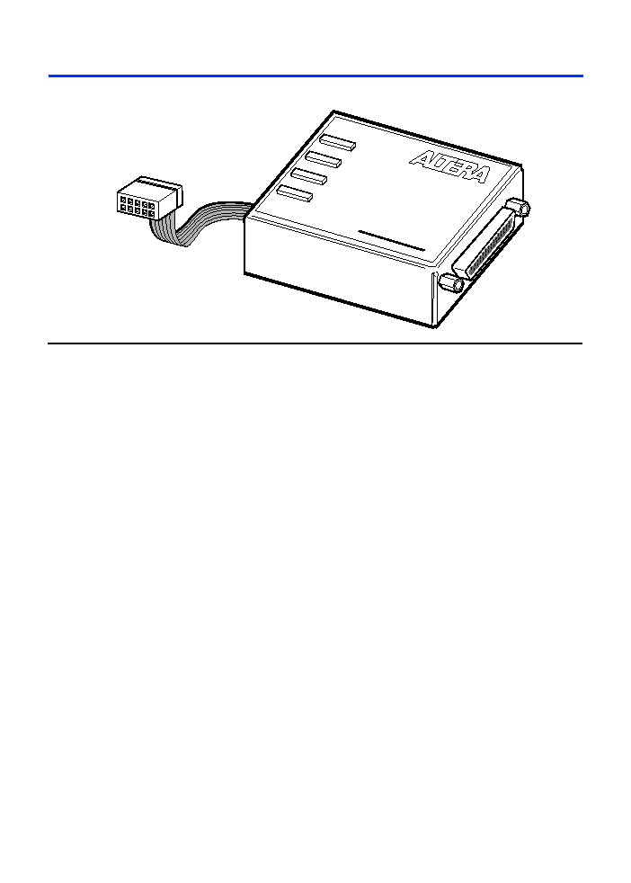
The BitBlaster
TM
serial download cable (ordering code: PL-BITBLASTER)
is a hardware interface to a standard RS-232 port (called a "COM port" on
PCs and either a "ttya port" or "ttyb port" on UNIX workstations). This
cable channels configuration data to FLEX 10K, FLEX 8000, and
FLEX 6000 devices, as well as programming data to MAX 9000 (including
MAX 9000A), MAX 7000S, MAX 7000A, and MAX 3000A devices. Because
design changes are downloaded directly to the device, prototyping is
easy, and multiple design iterations can be accomplished in quick
succession. See
Figure 1
.
2
Altera Corporation
BitBlaster Serial Download Cable Data Sheet
Figure 1. BitBlaster Serial Download Cable
Data Download Modes
The BitBlaster cable provides two data download modes:
Passive serial (PS) mode--Used for configuring FLEX 10K,
FLEX 8000, and FLEX 6000 devices
JTAG mode--Industry-standard JTAG boundary-scan test
(BST) circuitry (compliant with IEEE Std. 1149.1-1990)
implemented for programming or configuring FLEX 10K,
MAX 9000, MAX 7000S, MAX 7000A, and MAX 3000A devices.
BitBlaster Connections
Data is downloaded from the computer's RS-232 port through the
BitBlaster cable to the circuit board via the connections described in
this section.
1
To configure/program 3.3-V devices (e.g., FLEX 10KA,
FLEX 10KB, FLEX 10KE, MAX 7000A, and MAX 3000A
devices) using the BitBlaster cable, connect the cable's VCC
pin to a 5.0-V power supply and the device to a 3.3-V power
supply. 3.3-V Altera devices have 5.0-V tolerant inputs, so
the BitBlaster cable's 5.0-V output will not harm these 3.0-V
devices. The pull-up resistors should be connected to the
5.0-V power supply.
POWER
DONE
BUSY
ERROR
B
IT
B
LASTER
25-Pin
Female
RS-232
Port
10-Pin
Female
Plug
Æ
Altera Corporation
3
BitBlaster Serial Download Cable Data Sheet
D
e
ve
l
opm
e
n
t
13
T
o
ol
s
BitBlaster Female Port & Plug Connections
The 25-pin female port connects to an RS-232 port with a standard
serial cable. See
Table 1
.
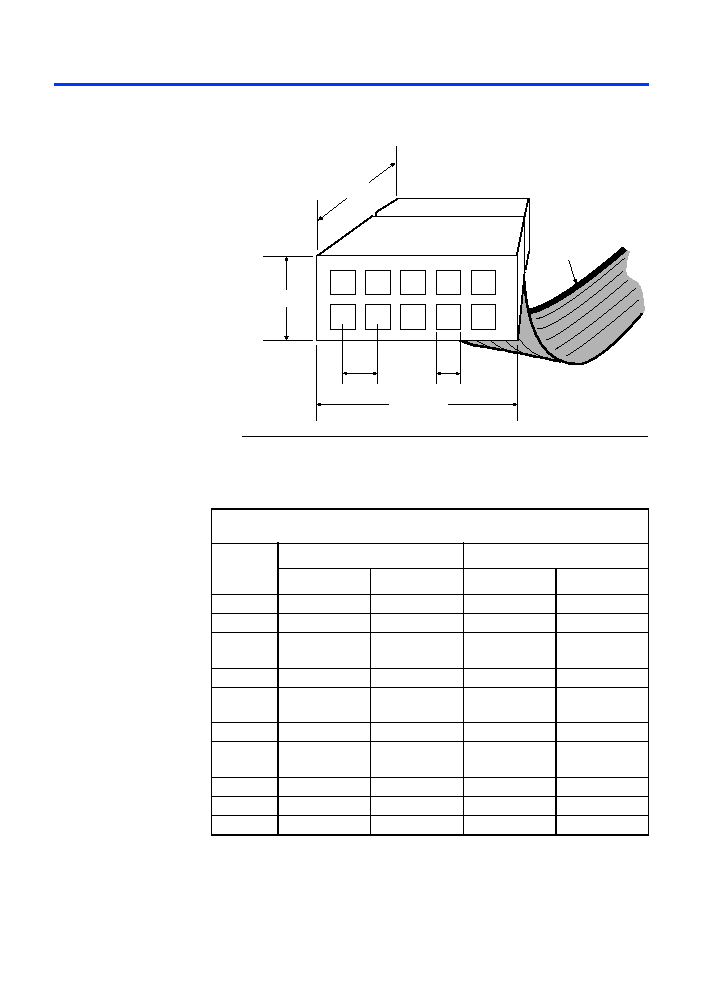
The 10-pin female plug connects to a 10-pin male header on the
circuit board containing the target device(s).
Figure 2
shows the
dimensions for the 10-pin female plug.
Table 1. BitBlaster 25-Pin Serial Port Pin-Outs
Pin
Signal Name
Description
2
tx
Transmit data
3
rx
Receive data
4
rts
Request to send
5
cts
Clear to send
6
dsr
Data set ready
7
GND
Signal ground
20
dtr
Data terminal ready
4
Altera Corporation
BitBlaster Serial Download Cable Data Sheet
Figure 2. BitBlaster 10-Pin Female Plug Dimensions
Dimensions are shown in inches. The spacing between pin centers is 0.1 inch.
Table 2
identifies the 10-pin female plug's pin names for the
corresponding download mode.
0.250 Typ.
0.700 Typ.
0.425 Typ.
0.100 Sq.
1
2
3
4
5
6
7
8
9
10
0.025 Sq.
Color Strip
Table 2. BitBlaster Female Plug's Pin Names & Download Modes
Pin
JTAG Mode
PS Mode
Signal Name
Description
Signal Name
Description
1
TCK
Clock signal
DCLK
Clock signal
2
GND
Ground
GND
Ground
3
TDO
Data from
device
CONF_DONE
Configuration
done
4
VCC
Power supply
VCC
Power supply
5
TMS
JTAG state
machine control
nCONFIG
Configuration
control
6
NC
No connect
NC
No connect
7
NC
No connect
nSTATUS
Configuration
status
8
NC
No connect
NC
No connect
9
TDI
Data to device
DATA0
Data to device
10
GND
Ground
GND
Ground
Altera Corporation
5
BitBlaster Serial Download Cable Data Sheet
D
e
ve
l
opm
e
n
t
13
T
o
ol
s
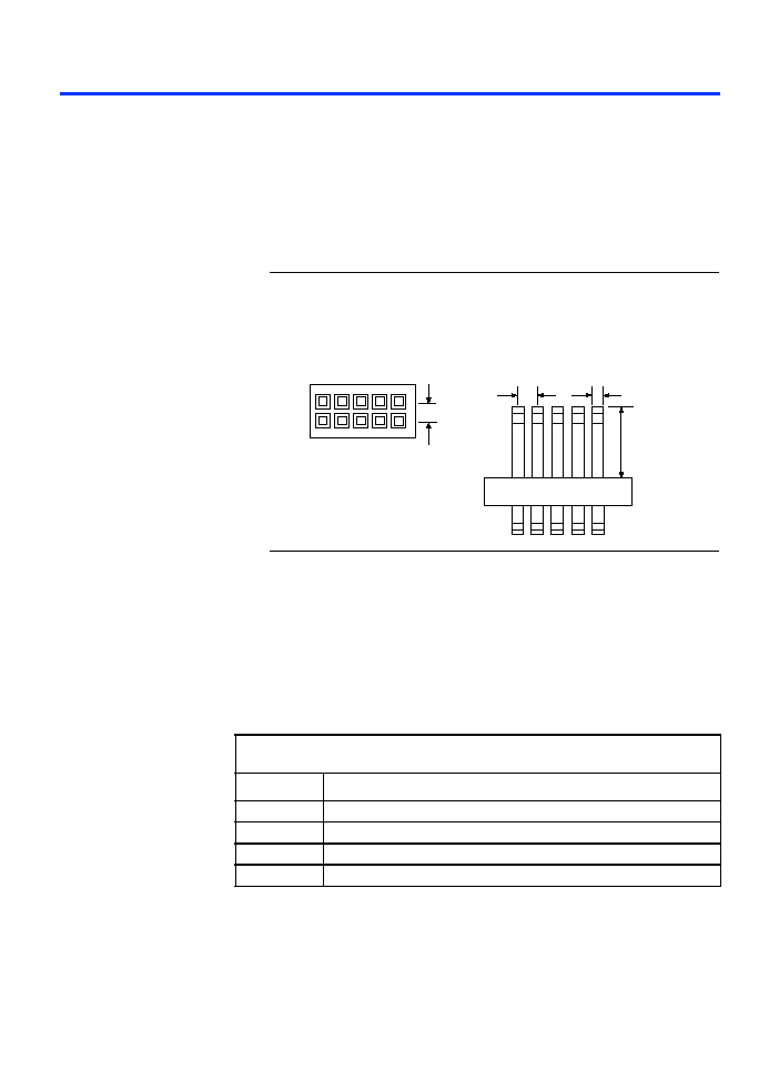
Circuit Board Header Connection
The BitBlaster 10-pin female plug connects to a 10-pin male header
on the circuit board. The 10-pin male header has two rows of five
pins connecting the circuit board to the device's programming or
configuration pins. The BitBlaster cable receives power and
downloads data via the male header.
Figure 3
shows the dimensions
of a typical 10-pin male header.
Figure 3. 10-Pin Male Header Dimensions
Dimensions are shown in inches.
1
The circuit board must supply V
CC
and ground to the
BitBlaster cable.
BitBlaster Status Lights
The BitBlaster status lights indicate the state of the device
configuration or programming. See
Table 3
.
0.025 Sq.
0.235
0.100
Side View
0.100
Top View
Table 3. BitBlaster Status Lights
Status Light
Description
POWER
Indicates a connection to the target system's power supply.
DONE
Indicates that device configuration or programming is complete.
BUSY
Indicates that device configuration or programming is in progress.
ERROR
Indicates error detection during configuration or programming.