The PG001M CMOS IC converts parallel-data signals from a low-
cost, 8-bit microprocessor or microcontroller into a serial-data format
compatible with the SLA7042M and SLA7044M power multi-chip
modules to drive unipolar PWM, high-current stepper motors. The
converter provides for five basic modes of operation:
1) normal, two-phase, full step (100% torque vector),
2) two-phase 'boosted' torque (141% torque vector),
3) half-step, constant torque operation (using a 2-1-2 output switching),
4) quarter-stepping utilizing ratioed currents for constant torque, and
5) microstepping (1/8
th
steps) for quiet, smooth, resonance-free motor
performance.
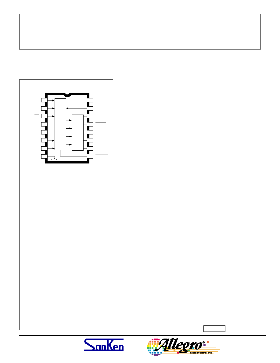
The PG001M is supplied in a low-cost 16-pin dual in-line plastic
package. It is rated for continuous operation over the temperature
range of -20
°
C to +85
°
C.
Always order by complete part number, PG001M .
FEATURES
s Intended For Use With SLA7042M or SLA7044M
Microstepping, Unipolar PWM, High-Current Motor Drivers
s Supports Five Stepper-Motor Operating Modes
s
µ
P-Compatible Inputs
Data Sheet
26112
PG001M
MODE
SELECT
. .
2
MODE
SELECT
. .
1
10
11
12
13
15
14
16
1
2
3
8
4
5
6
7
Dwg. PK-009
MONITOR
VECTOR
CONTROL
CCW/CW
RESET
STROBE
NO
CONNECT.
GROUND
9
CONTROL
SUPPLY
NOT USABLE
CONTROL LOGIC
PARALLEL-TO-SERIAL
CONVERTER
NOT USABLE
CLOCK
IN
CLOCK
SERIAL
DATA
OUT
A
B
SERIAL
DATA
V DD
Supply Voltage, V
DD
.................... 7.0 V
Input Voltage Range,
V
I
................ -0.5 V to V
DD
+ 0.5 V
Input Current, I
I
.......................
±
10 mA
Output Voltage Range,
V
O
............... -0.5 V to V
DD
+ 0.5 V
Output Current, I
O
...................
±
15 mA
Operating Temperature Range,
T
A
.......................... -20
°
C to +85
°
C
Storage Temperature Range,
T
S
........................ -40
°
C to +150
°
C
CAUTION: CMOS devices have input static
protection but are susceptible to damage if
exposed to extremely high static electrical
charges.
ABSOLUTE MAXIMUM RATINGS
PARALLEL-TO-SERIAL
DATA CONVERTER
TM
PG001M
PARALLEL-TO-SERIAL
DATA CONVERTER
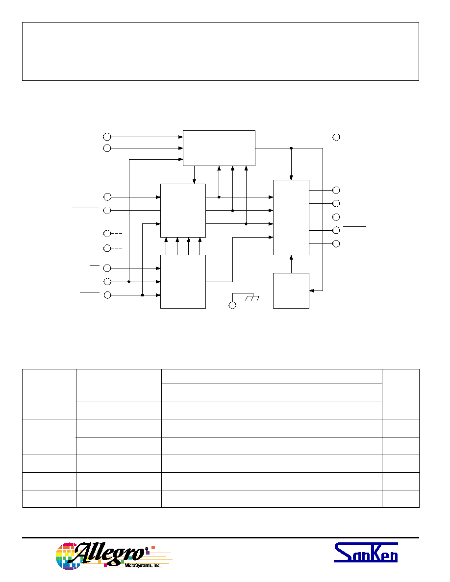
PG001M DESCRIPTION AND OPERATION
The PG001M is a CMOS step-motor control IC that
converts parallel-input signals from a microprocessor (
µ
P,
or microcontroller,
µ
C) to the serial-input data format
required for control of an SLA7042M or SLA7044M
microstepping, unipolar PWM, high-current motor driver.
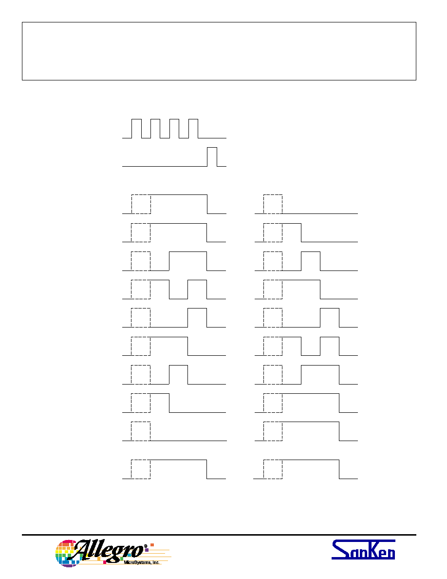
This control IC offers five basic modes of motor operation:
1) normal 2-phase, full-step (100% torque vector);
2) 2-phase, full-step 'boosted' torque (141% vector);
3) 1/2-step, constant torque operation
(i.e., 2-1-2 switching);
4) 1/4-step operation with current-ratioed constant
torque; and
5) smooth microstepping operation (1/8
th
step) for
resonance-free motor performance (constant torque
with eight output current ratios).
Three inputs (VC, MS
1
, and MS
2
) control these five
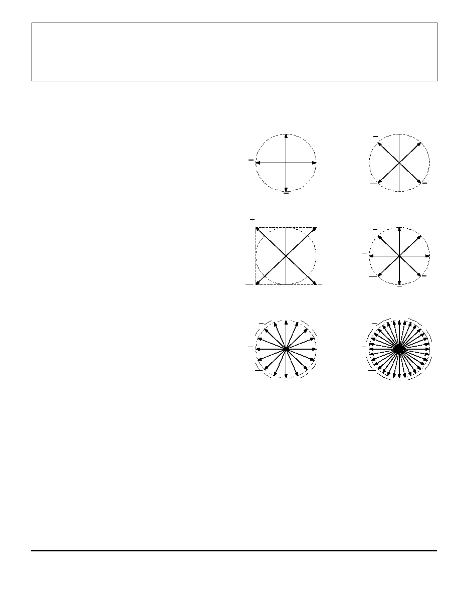
operational modes (as shown in figure 1); this enables
designers to change the drive method during movement to
realize optimal performance.
Initially, at start-up, the high-torque mode can provide
141% torque (the resulting vector of both motor windings
at 100% current). This enhances rapid acceleration (and
deceleration). Switching to quarter-stepping or
microstepping (after initial, startup acceleration) offers
smooth, resonance-free operation during the ramp-up
interval. The transition to quarter- or microstepping
should occur before the increasing step rate approaches the
motor resonance frequency (usually 100 to 200 Hz).
The modes of operation and current-control truth table
are listed on page 2; and there are two full-step, 2-phase
(2-2) operating modes. The VECTOR CONTROL input
(VC) can only be changed when MONITOR (MO, a
readback pin) is LOW and the PG001M is operating in the
full-step mode. Starting (or stopping) the step motor with
VC HIGH delivers the highest torque (141%) from the
motor, and is the extension of two outputs ON at 71.4%.
This 'half-step' rotor position corresponds to the state when
MO is LOW, and switching the control inputs to another
operating mode is allowed.
The PG001M accepts logic signals from the
µ
P and
converts these into the proper serial-data format required
to control the serial-data input lines of the SLA7042M or
SLA7044M microstepping power modules. The five
control inputs determine the various modes of operation.
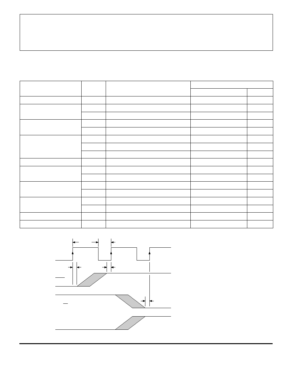
The CLOCK
OUT
, SERIAL DATA
A
, SERIAL DATA
B
, and
STROBE to the SLA7042/44M are synchronized to the
CLOCK
IN
of the PG001M; and the CLOCK
IN
frequency is
eight times the step rate (more to follow on the signal/
timing relationships).
The internal logic and oscillator combine to convert
the parallel input signals to 'bursts' of serial data from the
A
A
B
B
AB
AB
AB
AB
ONE-PHASE, FULL-STEP MODE
(WITHOUT PG001M)
TWO-PHASE, FULL-STEP MODE
(MS1 = L, MS2 = L, VC = L)
1/4-STEP MODE
(MS1 = L, MS2 = H, VC = X)
1/8-STEP MODE
(MS1 = H, MS2 = H, VC = X)
Dwg. OP-005
TWO-PHASE, FULL-STEP MODE
MAXIMUM TORQUE (141%)
(MS1 = L, MS2 = L, VC = H)
1/2-STEP MODE
CONSTANT TORQUE
(MS1 = H, MS2 = L, VC = X)
AB
AB
AB
AB
A
A
B
B
AB
AB
AB
AB
A
A
B
B
AB
AB
AB
AB
A
A
B
B
AB
AB
AB
AB
NOTE Mode change only allowed at half-step positions (refer to
upper right figure).
Figure 1 -- Current/Displacement Vectors