ATS673 and ATS674
ATS673LSE-DS
Worcester, Massachusetts 01615-0036 (508) 853-5000
115 Northeast Cutoff, Box 15036
www.allegromicro.com
Allegro MicroSystems, Inc.
AB SO LUTE MAX I MUM RAT INGS
Supply Voltage, V
CC
...........................................28 V
Reverse-Supply Voltage, V
RCC
........................18 V
Continuous Output Current, I
OUT
...................20 mA
Reverse-Output Current, I
ROUT
.......................50 mA
Operating Temperature
Ambient,
T
A
, Range L................ 40ºC to 150ºC
Maximum
Junction,
T
J(max)
........................165ºC
Storage Temperature, T
S
.................. 65ºC to 170ºC
Tight timing accuracy over operating temperature range
True zero-speed operation
TPOS (True Power-On State)
Air-gap-independent switchpoints
High immunity to vibration
Large operating air gaps
Operation with supply voltages down to 3.3 V
Digital output representing target profile
Single-chip solution for high reliability
Optimized Hall IC/magnet system
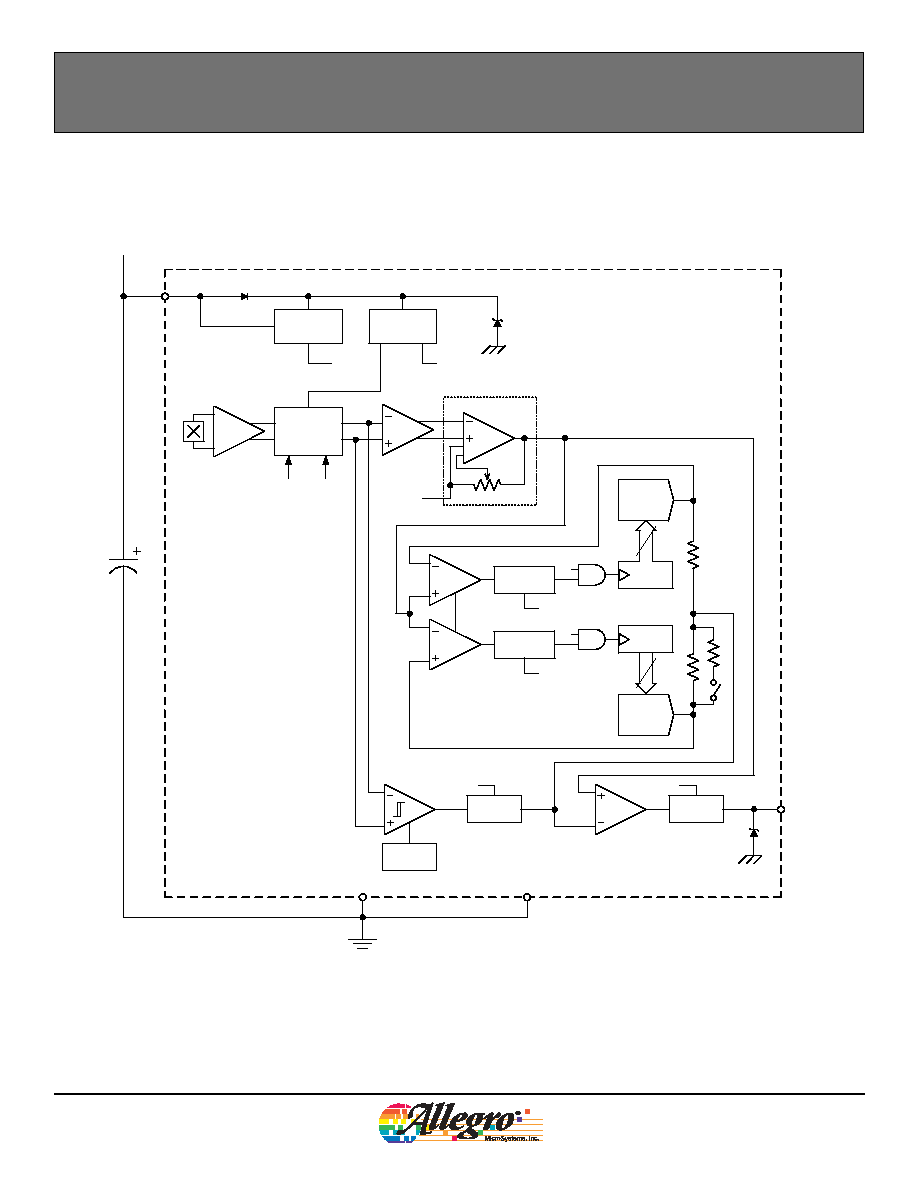
AGC and reference adjust circuit
Undervoltage lockout
Recognizing the increasingly stringent requirements for EMC/EMI in automotive
applications, Allegro has taken the necessary steps to design devices that are
capable of withstanding the effects of radiated and conducted transients. The
ATS673 and ATS674 devices have been designed specifically for this purpose.
Advanced circuitry on the die allows them to survive positive and negative
transient pulses on both the input and output.
The ATS673 and ATS674 devices retain all of the same characteristics as the
ATS671 and ATS672. The devices remain true zero-speed gear tooth sensors with
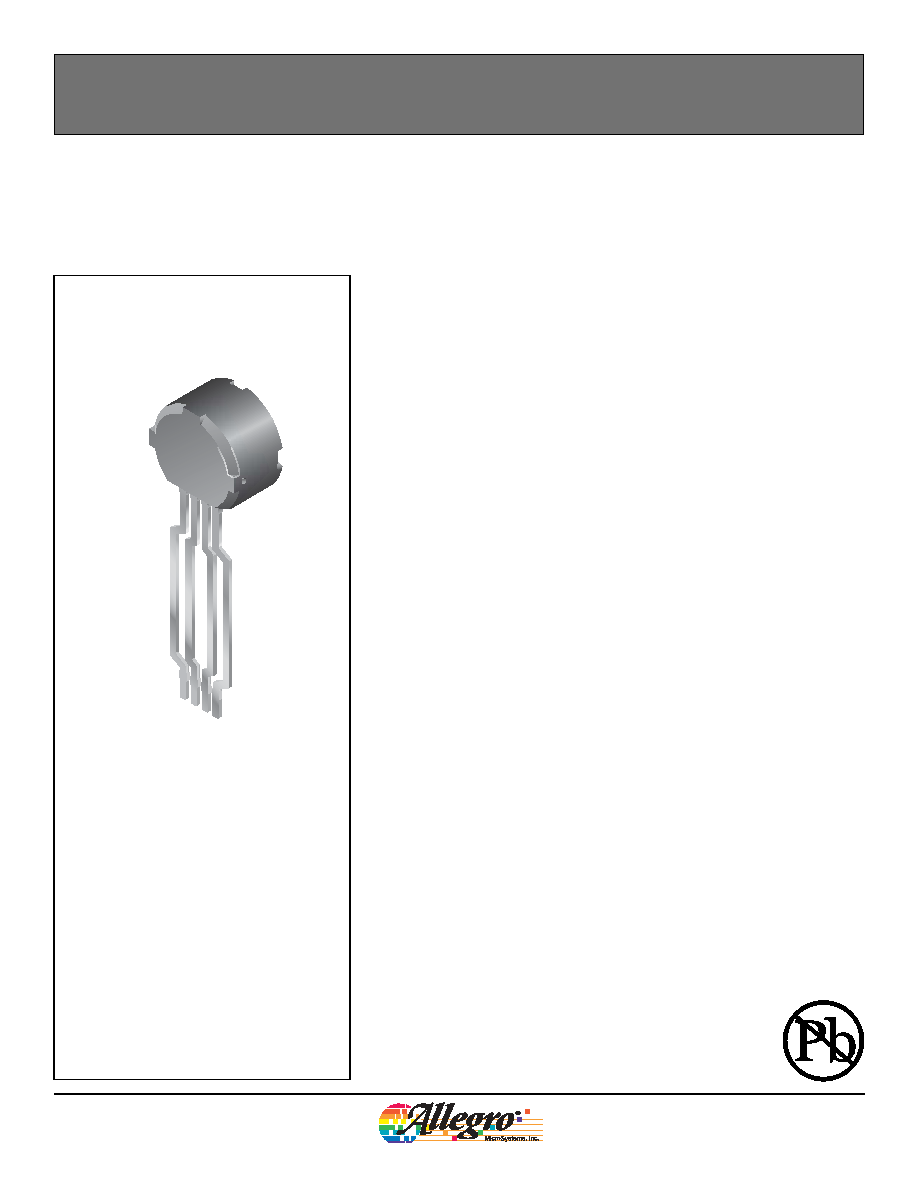
optimized Hall IC/magnet configuration in an SIP (single in-line package). The
SIP assembly consists of a molded package that holds together a samarium cobalt
magnet, a pole piece, and a true zero-speed Hall IC that has been optimized to the
magnetic circuit.
The sensor incorporates a single element Hall IC that switches in response to
magnetic signals created by a ferrous target. The IC contains a sophisticated
digital circuit designed to eliminate the detrimental effects of magnet and system
offsets. Signal processing is used to provide zero-speed performance independent
of air gap and also to dynamically adapt device performance to the typical
operating conditions found in automotive applications, particularly cam sensing
applications (reduced vibration sensitivity).
High-resolution (9-bit) peak detecting DACs are used to set the adaptive switching
thresholds of the devices, ensuring high accuracy even in the presence of gear
eccentricity. Hysteresis in the thresholds reduces the negative effects of anomalies
in the magnetic signal (such as magnetic overshoot) associated with the targets
used in many automotive applications. The ATS673 and 674 also include a low
bandwidth filter that increases the noise immunity and the signal to noise ratio of
the sensor.
Two options are available for output polarity, low over tooth (LT) and high over
tooth (HT). For applications requiring absolute accuracy use the ATS674. The
ATS673 should be used for targets with high wobble.
Self-Calibrating TPOS Gear Tooth Sensor Optimized for
Automotive Cam Sensing Applications
Features and Benefits
Package SE, 4-pin Through Hole
1. VCC
2. VOUT
3. TEST
4. GND
1
2
3
4
4
ATS673LSE-DS
Worcester, Massachusetts 01615-0036 (508) 853-5000
115 Northeast Cutoff, Box 15036
www.allegromicro.com
Allegro MicroSystems, Inc.
Self-Calibrating TPOS Gear Tooth Sensor Optimized for Automotive Cam Sensing Applications
ATS673 and ATS674
OPERATING CHARACTERISTICS
Valid at T
A
= 40°C to 150°C, T
J
T
J(max)
, over full range of AG, unless otherwise noted
Characteristic
Symbol
Test Conditions
Min.
Typ.
1
Max.
Units
Continued on the next page...
ELECTRICAL CHARACTERISTICS
Supply Voltage
V
CC
Operating; T
J
< T
J(Max)
3.3
26.5
V
Undervoltage Lockout
V
CCUV
<V
CC(Min)
V
Supply Zener Clamp Voltage
V
ZSupply
I
CC
= I
CC(Max)
+ 3 mA, T
A
= 25°C
28
31
35
V
Supply Zener Current
2
I
ZSupply
V
Supply
= 27 V
14
mA
Supply Current
I
CC
Output = OFF or ON
3
6.5
11
mA
Reverse Supply Current
I
RCC
V
RCC
= 18 V
5
10
mA
POWER-ON CHARACTERISTICS
Power-On Time
3
t
PO
Gear Speed < 100 rpm; V
CC
> V
CC(Min)
500
µs
OUTPUT CHARACTERISTICS
Low Output Voltage
V
OUT(Sat)
I
SINK
= 15 mA, Output = ON
200
450
mV
Output Zener Voltage
V
ZOUT
I
OUT
= 3 mA, T
A
= 25°C
30
V
Output Current Limit
I
OUTLIM
Output = ON, V
OUT
= 12 V
35
57
90
mA
Output Leakage Current
I
OUTOFF
Output = OFF, V
OUT
= V
CC(Max)
10
µA
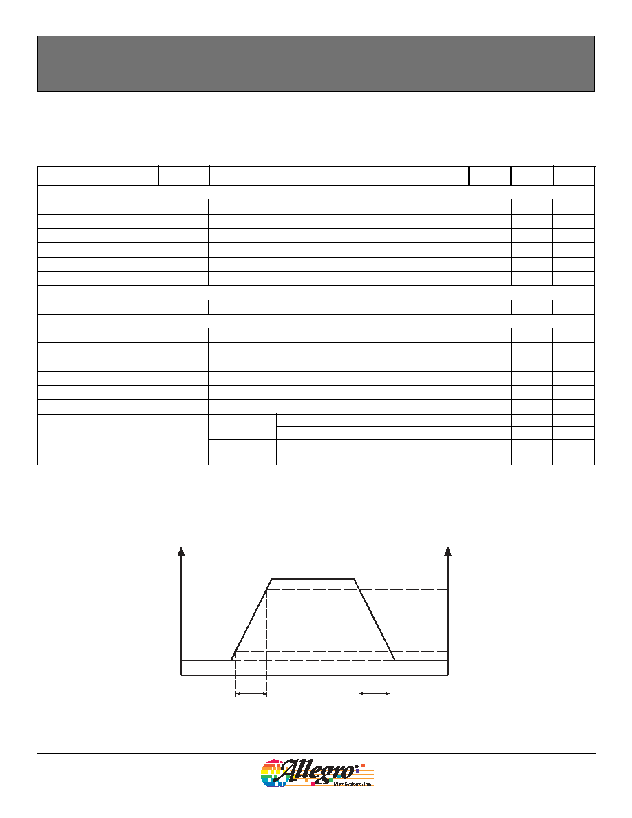
Output Rise Time
t
r
10/90% points; R
LOAD
= 500
, C
LOAD
= 10 pF, T
A
= 25°C
0.9
5
µs
Output Fall Time
t
f
10/90% points; R
LOAD
= 500
, C
LOAD
= 10 pF, T
A
= 25°C
0.5
5
µs
Output Polarity
V
OUT
HT device option
Over tooth
HIGH
V
Over valley
LOW
V
LT device option
Over tooth
LOW
V
Over valley
HIGH
V
t+
100
Output Rise and Fall Time
0
t
r
90
10
t
f
V
OUT(High)
V
OUT(Low)
V+
%

5
ATS673LSE-DS
Worcester, Massachusetts 01615-0036 (508) 853-5000
115 Northeast Cutoff, Box 15036
www.allegromicro.com
Allegro MicroSystems, Inc.
Self-Calibrating TPOS Gear Tooth Sensor Optimized for Automotive Cam Sensing Applications
ATS673 and ATS674
SWITCHPOINT CHARACTERISTICS
Tooth Speed
S
Tooth frequency, target generating sinusoidal signal
0
8
kHz
Bandwidth
BW
Corresponds to output switching frequency 3 dB
40
kHz
Operate
B
OP
ATS673 % of peak-to-peak, referenced to tooth signal,
AG < AG
(Max)
40
%
ATS674
30
%
Release
B
RP
ATS673 % of peak-to-peak, referenced to tooth signal,
AG < AG
(Max)
50
%
ATS674
40
%
CALIBRATION CHARACTERISTICS
4
Initial Calibration
Cal
IC
Quantity of rising edges required to complete edge detec-
tion calibration
3
edges
AGC Disable
Cal
AGC
Quantity of rising edges required to complete Automatic
Gain Control calibration
3
edges
Calibration Update
Cal
UPD
Quantity of rising edges required to update edge detection
calibration while running after initial calibration
Contin-
uous
edges
PERFORMANCE CHARACTERISTICS
3
TPOS Air Gap Range
5
AG
TPOS
TPOS functionality guaranteed
0.5
2.5
mm
Operational Air Gap Range
AG
TPOS guaranteed, output switching, running mode
0.5
2.5
mm
Extended Minimum Air Gap
6
AG
EXTMIN
Output switching, running mode; valleys may be detected
as teeth in this range
0.5
mm
Extended Maximum Air Gap
7
AG
EXTMAX
Output switching, running mode; teeth may be detected as
valleys in this range
2.5
5
mm
Relative Timing Accuracy
4,8
Err
ICREL
ATS673 During initial calibration; rising or falling edges,
gear speed = 1000 rpm, target eccentricity
< 0.1 mm
3
6
deg
ATS674
3
6
deg
Err
RELR
ATS673 Rising edges; after initial calibration, gear speed
= 1000 rpm, target eccentricity < 0.1 mm
0.5
0.8
deg
ATS674
0.4
0.8
deg
Err
RELF
ATS673 Falling edges; after initial calibration, gear speed
= 1000 rpm, target eccentricity < 0.1 mm
0.8
1.2
deg
ATS674
0.6
1.2
deg
Phase Delay
9
Err
SREL
After initial calibration, AG = 1.5 mm, T
A
= 25°C
1.6 x 10
4
deg/rpm
1
Typical values are taken at V
CC
= 12 V and T
A
= 25°C.
2
I
ZSupply(Max)
is equivalent to I
CCON(Max)
+ 3 mA.
3
Using reference target 8X.
4
The term edge refers to a mechanical edge, such as the side of a gear tooth, passing under the device. Rising edge: from valley to approaching tooth.
Falling edge: from tooth to approaching valley.
5
The TPOS Air Gap Range is the range of installation air gaps within which the TPOS (True Power-On State) function is guaranteed to correctly detect
a tooth when powered-on over a tooth and correctly detecting a valley when powered-on over a valley, using reference target 8X or equivalent, as
specified in the Target/Gear Parameters for Correct TPOS Operation section in this document.
6
The Extended Minimum Air Gap is a range of installation air gaps, smaller than AG
(Min)
, within which the the device will accurately detect target fea-
tures but TPOS is NOT guaranteed to be fully accurate, possibly evaluating the initial valley as a tooth.
7
The Extended Maximum Air Gap is an extended range of installation air gaps, greater than AG
(Max)
, within which the the device will accurately detect
target features but TPOS is not guaranteed to be fully accurate, possibly evaluating the intiial tooth as a valley.
8
Relative Timing Accuracy is the change in edge position before the resulting change in device output; for a single device, over the full Operational Air
Gap Range, AG, and Operating Ambient Temperature, T
A
, range.
9
Phase Delay is the change in edge position at detection, through the full operational Tooth Speed, S, range for a single device, and at a single ambi-
ent temperature, T
A
, and installation air gap, AG.
OPERATING CHARACTERISTICS, continued
Valid at T
A
= 40°C to 150°C, T
J
T
J(max)
, over full range of AG, unless otherwise noted
Characteristic
Symbol
Test Conditions
Min.
Typ.
1
Max.
Units