
8925
3-PHASE BRUSHLESS DC MOTOR CONTROLLER/DRIVER
WITH LINEAR CURRENT CONTROL
AND POWER DMOS OUTPUTS
DISCONTINUED PRODUCT
-- FOR REFERENCE ONL
Y
POWER
GROUND
6
5
4
3
2
1
44
43
42
41
40
7
8
9
10
11
12
13
14
15
16
17
29
30
39
38
37
36
35
34
33
32
31
28
27
26
25
24
23
22
21
20
19
18
V
CC
POWER
GROUND
POWER
GROUND
POWER
GROUND
V
BB
CHARGE PUMPS
SEQUENCING
AND CONTROL
CIRCUITRY
V
SENSE
BRAKE
COMP.
H
1
H
3
H
2
LOAD SUPPLY
NC
NC
LOGIC GROUND
NC
A
OUT
B
OUT
OUT
C
ENABLE
FAULT
POLE
TACH
NC
LOGIC SUPPLY
ERROR AMP
SUB
SUB
+
REFERENCE
3-PHASE BRUSHLESS DC MOTOR CONTROLLER/DRIVER
WITH LINEAR CURRENT CONTROL
AND POWER DMOS OUTPUTS
The A8925CEB is a DMOS three-phase brushless dc motor con-
troller/driver designed for use in Winchester disk drives and other data
storage applications. The power output stages are capable of
�
4 A
output currents and have DMOS power outputs with less than 0.25
r
DS(on)
for low power dissipation. Intrinsic ground clamp and flyback
diodes protect the output drivers when switching inductive loads.
Thermal shutdown circuitry is provided to protect the device from ex-
cessive junction temperature.
A transconductance amplifier is used to linearly regulate the load
current and control motor speed. Internal current-sensing circuitry
eliminates the need for external sense resistors. Analog and digital
control circuitry provide complete sequencing of the output drivers as
well as providing brake, disable, and tachometer functions. A FAULT
output flag indicates the presence of an under-voltage condition on the
12 V supply, excessive junction temperature, or an invalid Hall input
combination. The A8925CEB's commutation logic is compatible with
motors that have digital Hall-effect sensors with 120
�
of electrical
separation. Internal charge pump circuitry is provided to drive the N-
channel DMOS source drivers to their required gate voltages.
The A8925CEB is provided in a 44-lead PLCC power package for
surface-mount applications. The copper batwing provides for maxi-
mum allowable package power dissipation in the smallest possible
construction.
FEATURES
s
DMOS Outputs
s
Low r
DS(on)
- 0.25
Maximum
s
Linear Current Control
s
Internal Commutation Circuitry
s
Internal Current Sensing
s
Thermal Shutdown Circuitry
s
Under Voltage Detection Circuitry
s
Fault Output Flag
s
Power Surface-Mount Package
Always order by complete part number: A8925CEB .
ABSOLUTE MAXIMUM RATINGS
AT T
A
= +25
�
C
Load Supply Voltage, V
BB
..................... 14 V
Output Current, I
OUT
..........................
�
4.0 A
Logic Supply Voltage, V
CC
..................... 14 V
Logic Input Voltage Range,
V
IN
................................ -0.3 V to +6.0 V
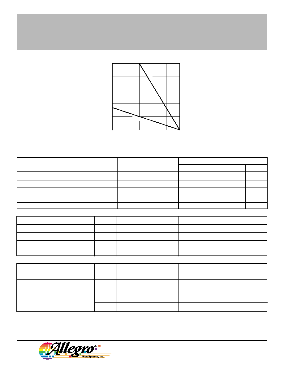
Package Power Dissipation,
P
D
......................................... See Graph
Operating Temperature Range,
T
A
..................................... 0
�
C to +70
�
C
Junction Temperature, T
J
............... +150
�
C
Storage Temperature Range,
T
S
................................ -55
�
C to +150
�
C
Fault conditions that produce excessive
junction temperature will activate device thermal
shutdown circuitry. These conditions can be
tolerated, but should be avoided.
Output current rating may be restricted to a value
determined by system concerns and factors.
These include: system duty cycle and timing,
ambient temperature, and use of any heatsinking
and/or forced cooling. For reliable operation, the
specified maximum junction temperature should
not be exceeded.
Dwg. PP-034
Data Sheet
26301.30
8925
115 Northeast Cutoff, Box 15036
Worcester, Massachusetts 01615-0036 (508) 853-5000
8925
3-PHASE BRUSHLESS DC MOTOR CONTROLLER/DRIVER
WITH LINEAR CURRENT CONTROL
AND POWER DMOS OUTPUTS
50
75
100
125
150
ALLOWABLE PACKAGE POWER DISSIPATION IN WATTS
TEMPERATURE IN
�
C
25
Dwg. GP-020B
12.5
2.5
0
10
7.5
5.0
R = 30
�
C/W
JA
R = 6
�
C/W
JT
ELECTRICAL CHARACTERISTICS AT T
A
= +25
�
C, V
CC
= V
BB
=
12 V
Limits
Characteristic
Symbol
Test Conditions
Min.
Typ.
Max.
Units
Logic Supply Voltage
V
CC
Operating
10
12
14
V
Load Supply Voltage
V
BB
Operating
10
12
14
V
Supply Current
I
CC
Operating
--
30
50
mA
V
ENABLE
= 0 V
--
2.0
4.0
mA
Thermal Shutdown
T
J
--
165
--
�
C
Output Drivers
Output ON Resistance
r
DS(on)
I
OUT
=
�
4.0 A, Pulse Test
--
0.20
0.25
Output Sustaining Voltage
V
DS(sus)
I
OUT
= 4.0 A, L = 2 mH
14
--
--
V
Clamp Diode Forward Voltage
V
F
I
F
=
�
4.0 A
--
1.5
2.0
V
Output Leakage Current
I
DSX
V
OUT
= 14 V
--
10
300
�
A
V
OUT
= 0 V
--
-10
-300
�
A
Control Logic
Logic Input Voltage
V
IN(0)
ENABLE, POLE
--
--
0.8
V
V
IN(1)
2.4
--
--
V
Logic Input Voltage
V
IN(0)
BRAKE
--
--
0.8
V
V
IN(1)
3.0
--
--
V
Logic Input Current
I
IN(0)
V
IN
= 0.8 V
--
--
-1.0
�
A
I
IN(1)
V
IN
= 2.4 V
--
--
1.0
�
A
NOTE: Negative current is defined as coming out of (sourcing) the specified device terminal.
Continued next page...
Copyright � 1990, 1995 Allegro MicroSystems, Inc.

8925
3-PHASE BRUSHLESS DC MOTOR CONTROLLER/DRIVER
WITH LINEAR CURRENT CONTROL
AND POWER DMOS OUTPUTS
Logic Output Voltage
V
OUT(0)
I
OUT
= 3 mA
--
--
0.8
V
V
OUT(1)
I
OUT
= -50
�
A
2.0
--
--
V
Error Amplifier
Input Bias Current
I
IB
V
CM
= 0.01 V
--
5.0
10
�
A
Input Offset Voltage
V
OS
V
CM
= 1.0 V
--
3.0
5.0
mV
Input Common-Mode Voltage Range
V
IC
0.01
--
6.0
V
Error Voltage Gain
A
VD
V
S OUT
/ V
S IN
, V
CM
= 1.0 V
--
80
--
dB
Unity Gain Bandwidth
BW
--
1.0
--
MHz
Common-Mode Rejection Ratio
CMRR
--
80
--
dB
Power Supply Rejection Ratio
PSRR
--
50
--
dB
Miscellaneous
Current Sense Gain
A
iCS
I
OUT
= -1.0 A
1/1k
1/1.2k
1/1.4k
--
Current-Sense Matching
--
I
OUT
= -1.0 A
--
�
3.0
�
5.0
%
Under-Voltage Trip Point
V
CC
8.0
--
9.5
V
Hall Input Current
I
IN(0)
V
IN
= 0 V
--
-500
-1000
�
A
I
IN(1)
V
IN
= 5.0 V
--
-250
-500
�
A
Hall Input Threshold
V
IN
--
3.8
--
V
Hall Input Pull-Up Resistance
R
PU
--
25
--
k
NOTE: Negative current is defined as coming out of (sourcing) the specified device terminal.
ELECTRICAL CHARACTERISTICS CONTINUED
Limits
Characteristic
Symbol
Test Conditions
Min.
Typ.
Max.
Units
(FAULT, TACH)
X = Irrelevant
Z = High Impedance
Hall Sensor Inputs
Outputs
H
1
H
2
H
3
ENABLE BRAKE FAULT
OUT
A
OUT
B
OUT
C
High
Low
High
High
High
High
High
Low
Z
High
Low
Low
High
High
High
High
Z
Low
High
High
Low
High
High
High
Z
High
Low
Low
High
Low
High
High
High
Low
High
Z
Low
High
High
High
High
High
Low
Z
High
Low
Low
High
High
High
High
Z
Low
High
High
High
High
High
High
Low
Z
Z
Z
Low
Low
Low
High
High
Low
Z
Z
Z
X
X
X
Low
High
X
Z
Z
Z
X
X
X
X
Low
X
Low
Low
Low
COMMUTATION TRUTH TABLE

115 Northeast Cutoff, Box 15036
Worcester, Massachusetts 01615-0036 (508) 853-5000
8925
3-PHASE BRUSHLESS DC MOTOR CONTROLLER/DRIVER
WITH LINEAR CURRENT CONTROL
AND POWER DMOS OUTPUTS
Term.
Terminal Name
Function
1
OUT
B
Power DMOS output.
2
LOGIC SUPPLY
V
CC
; low-current 12 V supply for the logic.
3
LOGIC GROUND
Low-level logic ground.
4
OUT
C
Power DMOS output.
6
ENABLE
Active high chip enable.
7�17
POWER GROUND
Power ground and thermal heat sink.
18
V
SENSE
External precision resistor for sense-FET current.
19
COMP.
Compensation; error amplifier output.
20
REFERENCE
V
REF
; voltage input that sets the power output current.
21
ERROR AMP.
Input that controls the current in the load.
22
LOAD SUPPLY
V
BB
; high-current 12 V supply for the voice-coil motor.
23
BRAKE
A logic low turns OFF all source drivers and turns ON all sink drivers (shorts the windings to
ground).
24
H
1
High-level input from a Hall sensor.
26
H
2
High-level input from a Hall sensor.
28
H
3
High-level input from a Hall sensor.
29�39
POWER GROUND
Power ground and thermal heat sink.
40
FAULT
A logic low at this output indicates a thermal shutdown, under -voltage fault, or an invalid Hall
input combination.
42
OUT
A
Power DMOS output.
43
TACH
Speed reference output; the H
1
Hall input divided by the number of motor poles.
44
POLE
Designates four- or eight-pole motor; Low = 4 pole, High = 8 pole.
FUNCTIONAL DESCRIPTION
Power Outputs (OUT
A
, OUT
B
, and
OUT
C
). The power outputs of the A8925CEB
are DMOS transistors with a maximum r
DS(on)
of 0.25
. Intrinsic ground clamp and flyback
diodes clamp transient voltage spikes when
switching inductive loads. Internal charge
pump circuitry is used to drive the gates of
the N-channel source drivers to their required
gate voltages.
Current Control. Current in the load is
monitored by an internal sense amplifier that
produces an output current that is approxi-
mately one twelve hundredth that of the load
current (see Figure). This current is output to
the V
SENSE
terminal and develops a voltage
V
SEQUENTIAL
LOGIC
CHARGE
PUMP
SENSE
AMPLIFIER
BB
SUB
ERROR
AMPLIFIER
V
SENSE
V
REF
COMP.
C
1
+
-
R
1
R
2
Dwg. EP-040
+
_
R
3
C
2
R
S
OUT
OUT
I .
1200
OUT
V
Continued next page...
TERMINAL FUNCTIONS

8925
3-PHASE BRUSHLESS DC MOTOR CONTROLLER/DRIVER
WITH LINEAR CURRENT CONTROL
AND POWER DMOS OUTPUTS
across R
S
that equals R
S
� I
LOAD
/1200. This
sense voltage (V
SENSE
) is compared to a ref-
erence voltage (V
REF
) and an error voltage is
developed that is gated in by the sequential
control logic to drive the gate of the appropri-
ate output sink transistor. A
transconductance control function is thus re-
alized where I
OUT
= V
REF
� 1200/R
S
. External
components C
1
, C
2
, R
1
, R
2
, and R
3
are com-
pensation components used to obtain optimal
response and settling of the current control
loop. Information on how to select these
components is available.
FAULT. The FAULT terminal when low
indicates the presence of one of three fault
conditions:
A)
An under-voltage condition
on the logic supply. The
trip point for this function is
between 8 and 9.5 volts.
B)
An invalid Hall input combi-
nation ... all inputs High or
all inputs Low.
C)
An excessive device
junction temperature. The
thermal shutdown circuitry
disables the output drivers
in addition to forcing the
FAULT output signal low.
TACH and POLE. In order to develop a
low-jitter tachometer signal (
TACH
) for use in
controlling motor speed, the A8925CEB di-
vides the frequency of the H
1
input by the
number of poles in the motor. This elimi-
nates the jitter caused by variations in Hall-
effect device placement , sensitivity, and
magnet strengths by always changing state
when looking at the same magnet/sensor
pair. The resulting
TACH
signal changes state
every mechanical revolution of the motor.
The POLE input sets the
TACH
signal for four-
pole motors when Low or eight-pole motors
when High.
HALL INPUTS (H
1
, H
2
, H
3
). The A8925CEB is configured for use
with open-collector Hall-effect devices. Internal 25 k
pull up resistors
to 10 volts are connected to these inputs.
ENABLE. The ENABLE terminal when Low puts the device in a
low current consumption, power-down mode. When ENABLE is High
the device is active.
BRAKE. When the BRAKE input goes Low the output source driv-
ers are disabled and the gates of the sink drivers are pulled high and
left floating. This achieves optimum passive braking performance
since the sink power DMOS output drivers are ON until the motor has
fully completed braking. The braking control circuitry operates off the
load supply (V
BB
) to allow it to remain operational during power loss by
using the back-EMF voltage of the motor as it's supply.
LOAD SUPPLY (V
BB
). This terminal is the power supply connec-
tion for the power output drivers and braking control circuitry. This ter-
minal should be decoupled with a large-value capacitor to absorb load
currents dumped back into the supply during the de-energization of
motor windings. These currents can cause the supply voltage to ex-
ceed the maximum voltage rating of the device if not properly
decoupled. The intrinsic ground clamp and flyback diodes will rectify
the motor's back-EMF voltage during power loss. In applications were
use of the motor's back-EMF voltage is desired a series diode should
be used to isolate this terminal from the logic supply (V
CC
). This is to
avoid dumping the charge back into the supply and therefor clamping
the voltage available from rectification of the motor's back-EMF
voltage.
LOGIC SUPPLY (V
CC
). This is the 12 volt supply terminal for the
A8925CEB and powers all circuitry except the power outputs and
brake control circuitry.
LOGIC GROUND. This must be connected to the power ground
terminals in systems that do not use separate power and logic
grounds.
POWER GROUND. Terminals 7 through 17 and 29 through 39
are webbed together and attach to the die mounting area to form a low
thermal resistance path to allow heat to be conducted out of the de-
vice. The power dissipation of the package can be further enhanced
by soldering these terminals to a large area of copper foil on the
printed wiring board.